[Click here for a PDF of this post with nicer formatting]
Disclaimer
Peeter’s lecture notes from class. May not be entirely coherent.
In slides
A review of systematic nodal analysis for a basic resistive circuit was outlined in slides, with a subsequent attempt to show how many similar linear systems can be modeled as circuits so that the same toolbox can be applied. This included blood flow through a body (and blood flow to the brain), a model of antenna interference in a portable phone, heat conduction in a one dimensional conductor under a heat lamp, and a few other systems.
This discussion reminded me of the joke where the farmer, the butcher and the physicist are all invited to talk at a beef convention. After meaningful and appropriate talks by the farmer and the butcher, the physicist gets his chance, and proceeds with “We begin by modeling the cow as a sphere, …”. The ECE equivalent of that appears to be a Kirchhoff circuit problem.
Mechanical structures example
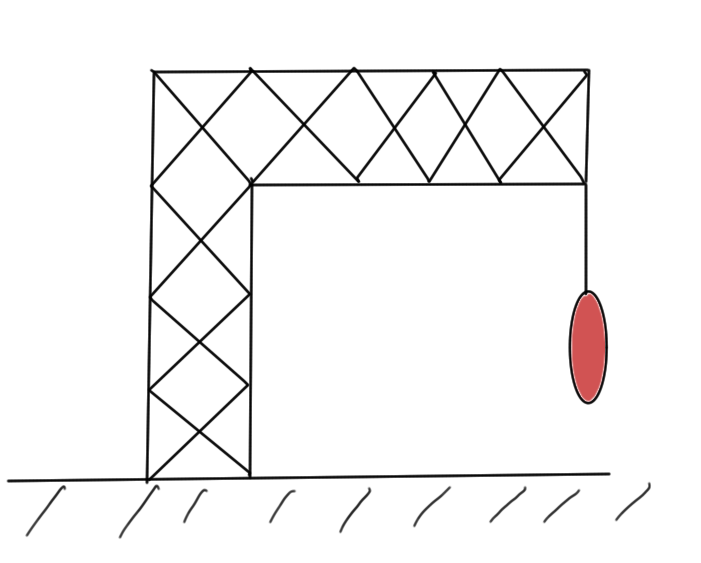
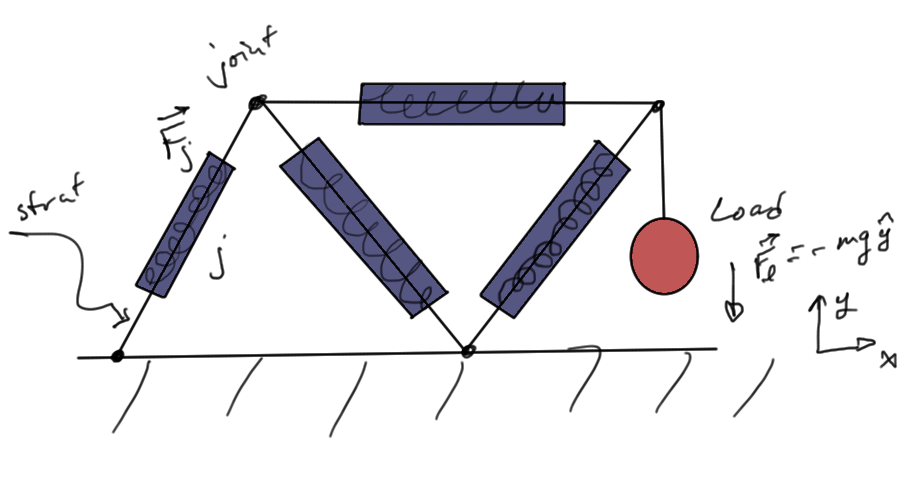
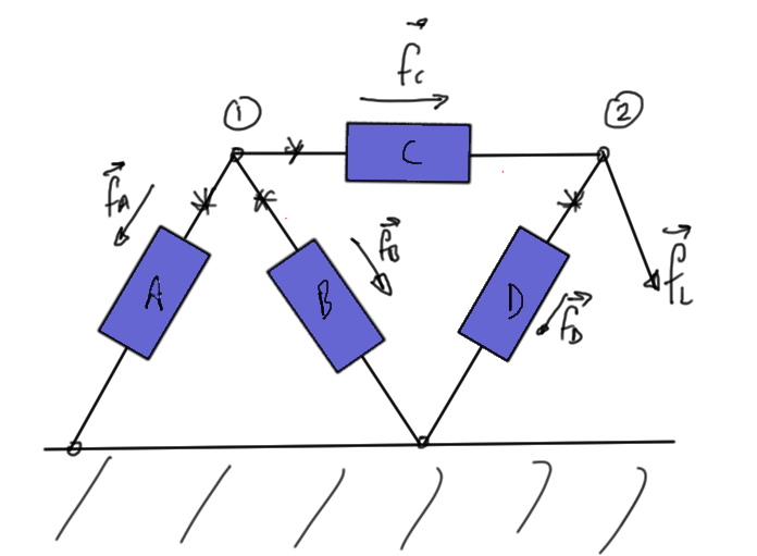
Continuing the application of circuits like linear systems to other systems, let’s consider a truss system as illustrated in fig. 1, or in the simpler similar system of fig. 2.
Our unknowns are
- positions of the joints after deformation \((x_i, y_i)\).
- force acting on each strut \(\BF_j = (F_{j,x}, F_{j,y})\).
The constitutive equations, assuming static conditions (steady state, no transients)
- Load force. \(\BF_L = (F_{L, x}, F_{L, y}) = (0, -m g)\).
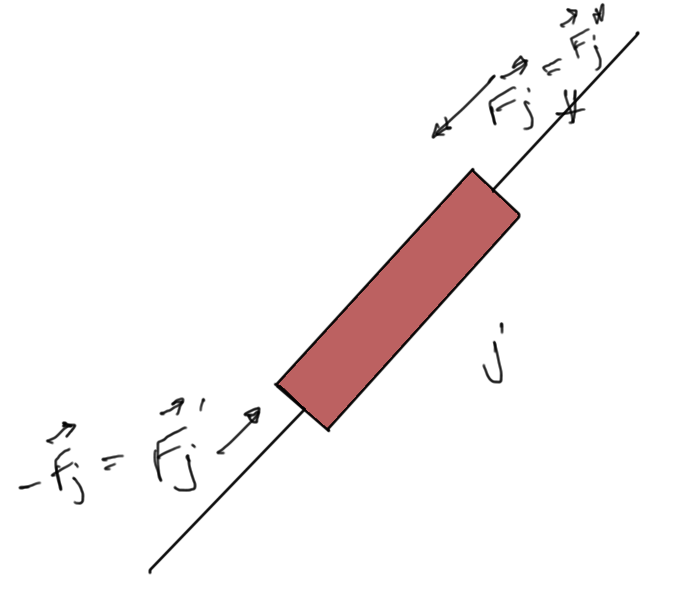
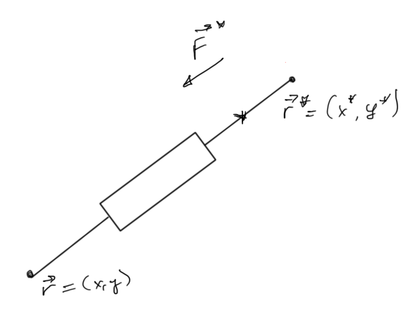
- Strut forces. Under static conditions the total resulting force on the strut is zero, so \(\BF’_j = -\BF_j\). For this problem it is redundant to label forces on both ends, so we mark the labeled end of the object with an asterisk as in fig. 3.
Consider a simple case
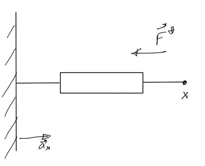
One strut as in fig. 4.
\begin{equation}\label{eqn:multiphysicsL1:20}
\BF^\conj = – \Ba_x
\underbrace{
\epsilon
}_{\text{constant, describes the beam elasticity, given}}
\biglr{
\underbrace{
L
}_{\text{unloaded length \(L = \Abs{x^\conj – 0}\), given}}
– L_0}
\end{equation}
The constitutive law for a general strut as in fig. 5 is
The force is directed along the unit vector
\begin{equation}\label{eqn:multiphysicsL1:40}
\Be = \frac{\Br^\conj – \Br}{\Abs{\Br^\conj – \Br}},
\end{equation}
and has the form
\begin{equation}\label{eqn:multiphysicsL1:60}
\BF^\conj = – \Be \epsilon \lr{ L – L_0 }.
\end{equation}
The value \(\epsilon\) may be related to Hooks’ constant, and \(L_0\) is given by
\begin{equation}\label{eqn:multiphysicsL1:80}
L = \Abs{\Br^\conj – \Br} = \sqrt{(x^\conj – x)^2 + (y^\conj – y)^2}.
\end{equation}
Observe that the relation between \(\BF^\conj\) and position is nonlinear!
Treatment of this system will be used as the prototype for our handling of other nonlinear systems.
Returning to the simple static system, and introducing force and joint labels as in fig. 6, we can examine the \textAndIndex{conservation law}, the balance of forces.
- At joint 1:\begin{equation}\label{eqn:multiphysicsL1:100}
\Bf_A + \Bf_B + \Bf_C = 0
\end{equation}or
\begin{equation}\label{eqn:multiphysicsL1:120}
\begin{aligned}
\Bf_{A,x} + \Bf_{B,x} + \Bf_{C,x} &= 0 \\
\Bf_{A,y} + \Bf_{B,y} + \Bf_{C,y} &= 0
\end{aligned}
\end{equation} - At joint 2:\begin{equation}\label{eqn:multiphysicsL1:140}
-\Bf_C + \Bf_D + \Bf_L = 0
\end{equation}or
\begin{equation}\label{eqn:multiphysicsL1:160}
\begin{aligned}
-\Bf_{C,x} + \Bf_{D,x} + \Bf_{L,x} &= 0 \\
-\Bf_{C,y} + \Bf_{D,y} + \Bf_{L,y} &= 0
\end{aligned}
\end{equation}
We have an equivalence
- Force \(\leftrightarrow\) Current.
- Force balance equation \(\leftrightarrow\) KCL
