[Click here for a PDF of this post with nicer formatting]
E and H plane directivities
In [2] directivities associated with the half power beamwidths are given as
\begin{equation}\label{eqn:taiAndPereira:20}
D_1 = \frac{\Abs{E_\theta}^2_{\textrm{max}}}{\inv{2} \int_0^\pi \Abs{E_\theta(\theta, 0)}^2 \sin\theta d\theta}
\end{equation}
\begin{equation}\label{eqn:taiAndPereira:40}
D_2 = \frac{\Abs{E_\phi}^2_{\textrm{max}}}{\inv{2} \int_0^\pi \Abs{E_\phi(\theta, \pi/2)}^2 \sin\theta d\theta},
\end{equation}
whereas [1] lists these as
\begin{equation}\label{eqn:taiAndPereira:60}
\inv{D_1} = \inv{2 \ln 2} \int_0^{\Theta_{1 r}/2} \sin\theta d\theta
\end{equation}
\begin{equation}\label{eqn:taiAndPereira:80}
\inv{D_2} = \inv{2 \ln 2} \int_0^{\Theta_{2 r}/2} \sin\theta d\theta.
\end{equation}
where the total directivity is given by the associated arithmetic mean formula
\begin{equation}\label{eqn:taiAndPereira:160}
\inv{D_0} = \inv{2}\lr{\inv{D_1} + \inv{D_2}}.
\end{equation}
This should follow from the far field approximation formula for \( U \). I intended to derive that result, but haven’t gotten to it. What follows instead are a few associated notes from a read of the paper, which I may revisit later to complete.
Short horizontal electrical dipole
Problem
In [2] a field for which directivities can be calculated exactly was used in comparisons of some directivity approximations
\begin{equation}\label{eqn:taiAndPereira:140}
\BE = E_0 \lr{ \cos\theta \cos\phi \thetacap – \sin\phi \phicap }.
\end{equation}
(Observe that an inverse radial dependence in \(E_0\) must be implied here for this to be a valid far-field representation of the field.)
Show that Tai & Pereira’s formula gives \( D_1 = 3 \), and \( D_2 = 1 \) respectively for this field.
Calculate the exact directivity for this field.
Answer
The field components are
\begin{equation}\label{eqn:taiAndPereira:180}
E_\theta = E_0 \cos\theta \cos\phi
\end{equation}
\begin{equation}\label{eqn:taiAndPereira:200}
E_\phi = -E_0 \sin\phi
\end{equation}
Using \ref{eqn:taiAndPereira:10} from the paper, the directivities are
\begin{equation}\label{eqn:taiAndPereira:220}
D_1 = \frac{2}{\int_0^\pi \cos^2 \theta \sin\theta d\theta}
= \frac{2}{\evalrange{-\inv{3}\cos^3\theta}{0}{\pi}}
= 3,
\end{equation}
and
\begin{equation}\label{eqn:taiAndPereira:240}
D_2
= \frac{2}{\int_0^\pi \sin\theta d\theta}
= \frac{2}{\evalrange{-\cos\theta}{0}{\pi}}
= 1.
\end{equation}
To find the exact directivity, first the Poynting vector is required. That is
\begin{equation}\label{eqn:taiAndPereira:260}
\begin{aligned}
\BP
&= \frac{
\Abs{E_0}^2
}{2 c \mu_0}
\lr{ \cos\theta \cos\phi \thetacap – \sin\phi \phicap }
\cross
\lr{ \rcap \cross \lr{ \cos\theta \cos\phi \thetacap – \sin\phi \phicap } } \\
&= \frac{
\Abs{E_0}^2
}{ 2 c \mu_0}
\lr{ \cos\theta \cos\phi \thetacap – \sin\phi \phicap }
\cross
\lr{ \cos\theta \cos\phi \phicap + \sin\phi \thetacap } \\
&= \frac{
\Abs{E_0}^2 \rcap
}{2 c \mu_0}
\lr{ \cos^2\theta \cos^2\phi + \sin^2\phi },
\end{aligned}
\end{equation}
so the radiation intensity is
\begin{equation}\label{eqn:taiAndPereira:280}
U(\theta, \phi) \propto \cos^2\theta \cos^2\phi + \sin^2\phi.
\end{equation}
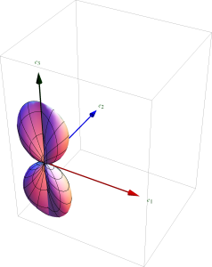
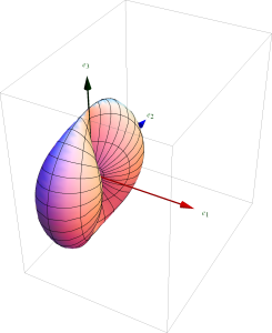
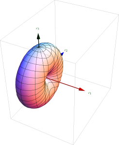
The \( \thetacap \), and \( \phicap \) contributions to this intensity, and the total intensity are all plotted in fig. 1, fig. 2, and fig. 3 respectively.
Given this the total radiated power is
\begin{equation}\label{eqn:taiAndPereira:300}
P_{\textrm{rad}} = \int_0^{2 \pi} \int_0^\pi
\lr{ \cos^2\theta \cos^2\phi + \sin^2\phi } \sin\theta d\theta d\phi
= \frac{8 \pi}{3}.
\end{equation}
Observe that the radiation intensity \( U \) can also be decomposed into two components, one for each component of the original \( \BE \) phasor.
\begin{equation}\label{eqn:taiAndPereira:320}
U_\theta = \cos^2 \theta \cos^2 \phi
\end{equation}
\begin{equation}\label{eqn:taiAndPereira:340}
U_\phi = \sin^2 \phi
\end{equation}
This decomposition allows for expression of the partial directivities in these respective (orthogonal) directions
\begin{equation}\label{eqn:taiAndPereira:360}
D_\theta = \frac{4 \pi U_\theta}{P_{\textrm{rad}}} = \frac{3}{2} \cos^2 \theta \cos^2 \phi
\end{equation}
\begin{equation}\label{eqn:taiAndPereira:380}
D_\phi = \frac{4 \pi U_\phi}{P_{\textrm{rad}}} = \frac{3}{2} \sin^2 \phi
\end{equation}
The maximum of each of these partial directivities is both \( 3/2 \), giving a maximum directivity of
\begin{equation}\label{eqn:taiAndPereira:400}
D_0 =
\evalbar{D_\theta}{{\textrm{max}}}
+\evalbar{D_\phi}{{\textrm{max}}} = 3,
\end{equation}
the exact value from the paper.
References
[1] Constantine A Balanis. Antenna theory: analysis and design. John Wiley & Sons, 3rd edition, 2005.
[2] C-T Tai and CS Pereira. An approximate formula for calculating the directivity of an antenna. IEEE Transactions on Antennas and Propagation, 24:235, 1976.


