[Click here for a PDF of this post with nicer formatting]
The problem set contained a circuit with constant voltage source that made the associated Nodal matrix non-symmetric. There was a hint that this source \( V_s \) and its internal resistance \( R_s \) can likely be replaced by a constant current source.
Here two voltage source configurations will be compared to a current source configuration, with the assumption that equivalent circuit configurations can be found.
First voltage source configuration
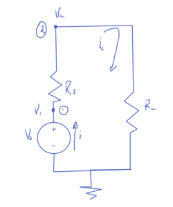
First consider the source and internal series resistance configuration sketched in fig. 1, with a purely resistive load.
The nodal equations for this system are
- \( -i_L + (V_1 – V_L) Z_s = 0 \)
- \( V_L Z_L + (V_L – V_1) Z_s = 0 \)
- \( V_1 = V_s \)
In matrix form these are
\begin{equation}\label{eqn:simpleNortonEquivalents:20}
\begin{bmatrix}
Z_s & -Z_s & -1 \\
-Z_s & Z_s + Z_L & 0 \\
1 & 0 & 0
\end{bmatrix}
\begin{bmatrix}
V_1 \\
V_L \\
i_L
\end{bmatrix}
=
\begin{bmatrix}
0 \\
0 \\
V_s
\end{bmatrix}
\end{equation}
This has solution
\begin{equation}\label{eqn:simpleNortonEquivalents:40}
V_L = V_s \frac{ R_L }{R_L + R_s}
\end{equation}
\begin{equation}\label{eqn:simpleNortonEquivalents:100}
i_L = \frac{V_s}{R_L + R_s}
\end{equation}
\begin{equation}\label{eqn:simpleNortonEquivalents:120}
V_1 = V_s.
\end{equation}
Second voltage source configuration
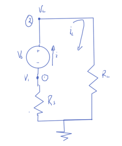
Now consider the same voltage source, but with the series resistance location flipped as sketched in fig. 2.
The nodal equations are
- \( V_1 Z_s + i_L = 0 \)
- \( -i_L + V_L Z_L = 0 \)
- \( V_L – V_1 = V_s \)
These have matrix form
\begin{equation}\label{eqn:simpleNortonEquivalents:60}
\begin{bmatrix}
Z_s & 0 & 1 \\
0 & Z_L & -1 \\
-1 & 1 & 0
\end{bmatrix}
\begin{bmatrix}
V_1 \\
V_L \\
i_L
\end{bmatrix}
=
\begin{bmatrix}
0 \\
0 \\
V_s
\end{bmatrix}
\end{equation}
This configuration has solution
\begin{equation}\label{eqn:simpleNortonEquivalents:50}
V_L = V_s \frac{ R_L }{R_L + R_s}
\end{equation}
\begin{equation}\label{eqn:simpleNortonEquivalents:180}
i_L = \frac{V_s}{R_L + R_s}
\end{equation}
\begin{equation}\label{eqn:simpleNortonEquivalents:200}
V_1 = -V_s \frac{ R_s }{R_L + R_s}
\end{equation}
Observe that the voltage at the load node and the current through this impedance is the same in both circuit configurations. The internal node voltage is different in each case, but that has no measurable effect on the external load.
Current configuration
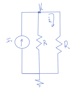
Now consider a current source and internal parallel resistance as sketched in fig. 3.
There is only one nodal equation for this circuit
- \( -I_s + V_L Z_s + V_L Z_L = 0 \)
The load node voltage and current follows immediately
\begin{equation}\label{eqn:simpleNortonEquivalents:80}
V_L = \frac{I_s}{Z_L + Z_s}
\end{equation}
\begin{equation}\label{eqn:simpleNortonEquivalents:140}
i_L = V_L Z_L = \frac{Z_L I_s}{Z_L + Z_s}
\end{equation}
The goal is to find a value for \( I_L \) so that the voltage and currents at the load node match either of the first two voltage source configurations. It has been assumed that the desired parallel source resistance is the same as the series resistance in the voltage configurations. That was just a guess, but it ends up working out.
From \ref{eqn:simpleNortonEquivalents:80} and \ref{eqn:simpleNortonEquivalents:40} that equivalent current source can be found from
\begin{equation}\label{eqn:simpleNortonEquivalents:160}
V_L = V_s \frac{ R_L }{R_L + R_s} = \frac{I_s}{Z_L + Z_s},
\end{equation}
or
\begin{equation}\label{eqn:simpleNortonEquivalents:220}
I_s
=
V_s \frac{ R_L (Z_L + Z_s)}{R_L + R_s}
=
\frac{V_s}{R_S} \frac{ R_s R_L (Z_L + Z_s)}{R_L + R_s}
\end{equation}
\begin{equation}\label{eqn:simpleNortonEquivalents:240}
\boxed{
I_s
=
\frac{V_s}{R_S}.
}
\end{equation}
The load is expected to be the same through the load, and is
\begin{equation}\label{eqn:simpleNortonEquivalents:n}
i_L = V_L Z_L =
= V_s \frac{ R_L Z_L }{R_L + R_s}
= \frac{ V_s }{R_L + R_s},
\end{equation}
which matches \ref{eqn:simpleNortonEquivalents:100}.
Remarks
The equivalence of the series voltage source configurations with the parallel
current source configuration has been demonstrated with a resistive load. This
is a special case of the more general Norton’s theorem, as detailed in [2] and
[1] \S 5.1. Neither of those references prove the theorem. Norton’s theorem allows the equivalent current and resistance to be calculated without actually solving the system. Using that method, the parallel resistance equivalent follows by summing all the resistances in the source circuit with all the voltage sources shorted. Shorting the voltage sources in this source circuit results in the same configuration. It was seen directly in the two voltage source configurations that it did not matter, from the point of view of the external load, which sequence the internal series resistance and the voltage source were placed in did not matter. That becomes obvious with knowledge of Norton’s theorem, since shorting the voltage sources leaves just the single resistor in both cases.
References
[1] J.D. Irwin. Basic Engineering Circuit Analysis. Macillian, 1993.
[2] Wikipedia. Norton’s theorem — wikipedia, the free encyclopedia, 2014. URL https://en.wikipedia.org/w/index.php?title=Norton\%27s_theorem&oldid=629143825. [Online; accessed 1-November-2014].


