[Click here for a PDF of this post with nicer formatting]
Disclaimer
Peeter’s lecture notes from class. These may be incoherent and rough.
Singular Jacobians
(mostly on slides)
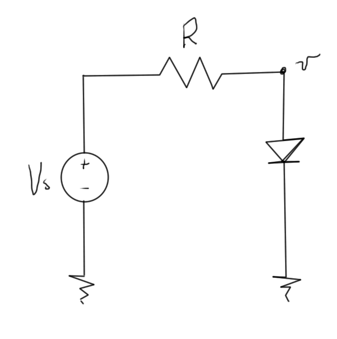
There is the possiblity of singular Jacobians to consider. FIXME: not sure how this system represented that. Look on slides.
\begin{equation}\label{eqn:multiphysicsL13:20}
\tilde{f}(v(\lambda), \lambda) = i(v) – \inv{R}( v – \lambda V_s ) = 0.
\end{equation}
An alternate continuation scheme uses
\begin{equation}\label{eqn:multiphysicsL13:40}
\tilde{F}(\Bx(\lambda), \lambda) = \lambda F(\Bx(\lambda)) + (1-\lambda) \Bx(\lambda).
\end{equation}
This scheme has
\begin{equation}\label{eqn:multiphysicsL13:60}
\tilde{F}(\Bx(0), 0) = 0
\end{equation}
\begin{equation}\label{eqn:multiphysicsL13:80}
\tilde{F}(\Bx(1), 1) = F(\Bx(1)),
\end{equation}
and for one variable, easy to compute Jacobian at the origin, or the original Jacobian at \( \lambda = 1 \)
\begin{equation}\label{eqn:multiphysicsL13:100}
\PD{x}{\tilde{F}}(x(0), 0) = I
\end{equation}
\begin{equation}\label{eqn:multiphysicsL13:120}
\PD{x}{\tilde{F}}(x(1), 1) = \PD{x}{F}(x(1))
\end{equation}
Simulation of dynamical systems
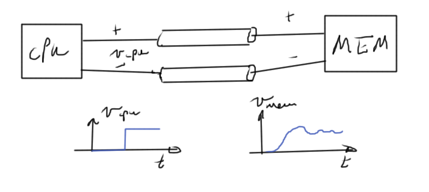
Example high level system in fig. 2.
Assembling equations automatically for dynamical systems
RC circuit
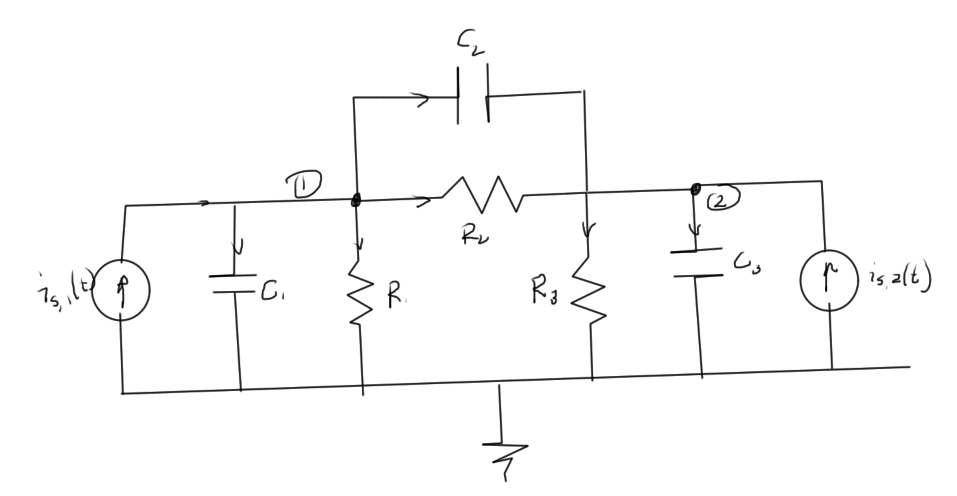
To demonstrate the method by example consider the RC circuit fig. 3 which has time dependence that must be considered
The unknowns are \( v_1(t), v_2(t) \).
The equations (KCLs) at each of the nodes are
- \(
\frac{v_1(t)}{R_1}
+ C_1 \frac{dv_1}{dt}
+ \frac{v_1(t) – v_2(t)}{R_2}
+ C_2 \frac{d(v_1 – v_2)}{dt}
– i_{s,1}(t) = 0
\) - \(
\frac{v_2(t) – v_1(t)}{R_2}
+ C_2 \frac{d(v_2 – v_1)}{dt}
+ \frac{v_2(t)}{R_3}
+ C_3 \frac{dv_2}{dt}
– i_{s,2}(t)
= 0
\)
This has the matrix form
\begin{equation}\label{eqn:multiphysicsL13:140}
\begin{bmatrix}
Z_1 + Z_2 & – Z_2 \\
-Z_2 & Z_2 + Z_3
\end{bmatrix}
\begin{bmatrix}
v_1(t) \\
v_2(t)
\end{bmatrix}
+
\begin{bmatrix}
C_1 + C_2 & -C_2 \\
– C_2 & C_2 + C_3
\end{bmatrix}
\begin{bmatrix}
\frac{dv_1(t)}{dt} \\
\frac{dv_2(t}{dt})
\end{bmatrix}
=
\begin{bmatrix}
1 & 0 \\
0 & 1
\end{bmatrix}
\begin{bmatrix}
i_{s,1}(t) \\
i_{s,2}(t)
\end{bmatrix}.
\end{equation}
Observe that the capacitor between node 2 and 1 is associated with a stamp of the form
\begin{equation}\label{eqn:multiphysicsL13:180}
\begin{bmatrix}
C_2 & -C_2 \\
-C_2 & C_2
\end{bmatrix},
\end{equation}
very much like the impedance stamps of the resistor node elements.
The RC circuit problem has the abstract form
\begin{equation}\label{eqn:multiphysicsL13:160}
G \Bx(t) + C \frac{d\Bx(t)}{dt} = B \Bu(t),
\end{equation}
which is more general than a state space equation of the form
\begin{equation}\label{eqn:multiphysicsL13:200}
\frac{d\Bx(t)}{dt} = A \Bx(t) + B \Bu(t).
\end{equation}
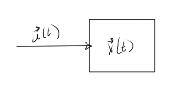
Such a system may be represented diagramatically as in fig. 4.
The \( C \) factor in this capacitance system, is generally not invertable. For example, if consider a 10 node system with only one capacitor, for which \( C \) will be mostly zeros.
In a state space system, in all equations we have a derivative. All equations are dynamical.
The time dependent MNA system for the RC circuit above, contains a mix of dynamical and algebraic equations. This could, for example, be a pair of equations like
\begin{equation}\label{eqn:multiphysicsL13:240}
\frac{dx_1}{dt} + x_2 + 3 = 0
\end{equation}
\begin{equation}\label{eqn:multiphysicsL13:260}
x_1 + x_2 + 3 = 0
\end{equation}
How to handle inductors
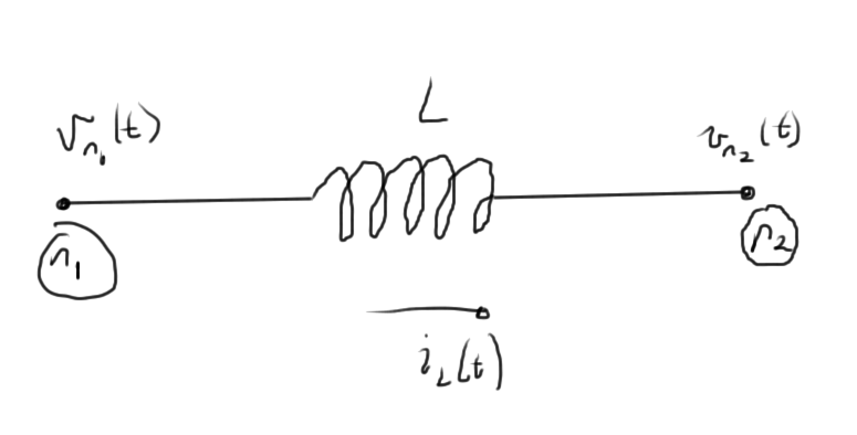
A pair of nodes that contains an inductor element, as in fig. 5, has to be handled specially.
The KCL at node 1 has the form
\begin{equation}\label{eqn:multiphysicsL13:280}
\cdots + i_L(t) + \cdots = 0,
\end{equation}
where
\begin{equation}\label{eqn:multiphysicsL13:300}
v_{n_1}(t) – v_{n_2}(t) = L \frac{d i_L}{dt}.
\end{equation}
It is possible to express this in terms of \( i_L \), the variable of interest
\begin{equation}\label{eqn:multiphysicsL13:320}
i_L(t) = \inv{L} \int_0^t \lr{ v_{n_1}(\tau) – v_{n_2}(\tau) } d\tau
+ i_L(0).
\end{equation}
Expressing the problem directly in terms of such integrals makes the problem harder to solve, since the usual differential equation toolbox cannot be used directly. An integro-differential toolbox would have to be developed. What can be done instead is to introduce an additional unknown for each inductor current derivative \( di_L/dt \), for which an additional MNA row is introduced for that inductor scaled voltage difference.
Numerical solution of differential equations
Consider the one variable system
\begin{equation}\label{eqn:multiphysicsL13:340}
G x(t) + C \frac{dx}{dt} = B u(t),
\end{equation}
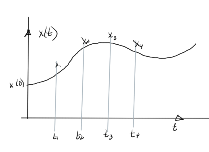
given an initial condition \( x(0) = x_0 \). Imagine that this system has the solution sketched in fig. 6.
Very roughly, the steps for solution are of the form
- Discretize time
- Aim to find the solution at \( t_1, t_2, t_3, \cdots \)
- Use a finite difference formula to approximate the derivative.
There are various schemes that can be used to discretize, and compute the finite differences.
Forward Euler method
\index{forward Euler method}
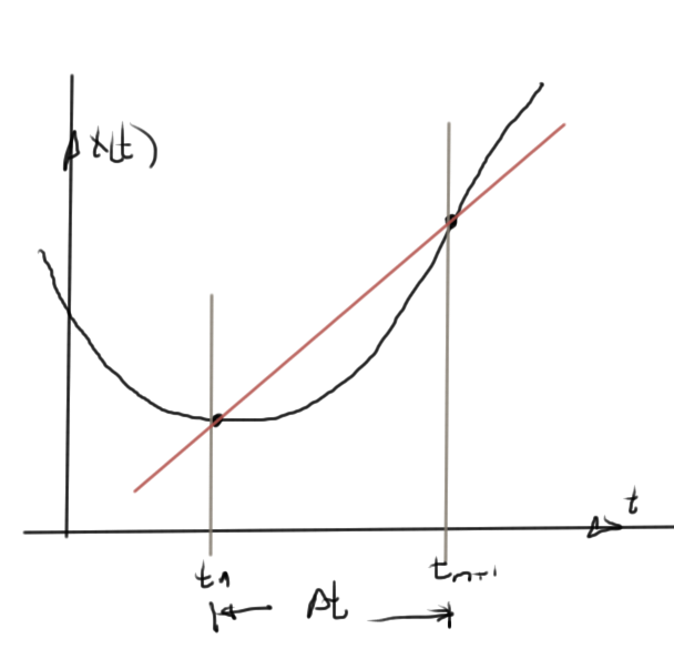
One such scheme is to use the forward differences, as in fig. 7, to approximate the derivative
\begin{equation}\label{eqn:multiphysicsL13:360}
\dot{x}(t_n) \approx \frac{x_{n+1} – x_n}{\Delta t}.
\end{equation}
Introducing this into \ref{eqn:multiphysicsL13:340} gives
\begin{equation}\label{eqn:multiphysicsL13:350}
G x_n + C \frac{x_{n+1} – x_n}{\Delta t} = B u(t_n),
\end{equation}
or
\begin{equation}\label{eqn:multiphysicsL13:380}
C x_{n+1} = \Delta t B u(t_n) – \Delta t G x_n + C x_n.
\end{equation}
The coefficient \( C \) must be invertable, and the next point follows immediately
\begin{equation}\label{eqn:multiphysicsL13:381}
x_{n+1} = \frac{\Delta t B}{C} u(t_n)
+ x_n \lr{ 1 – \frac{\Delta t G}{C} }.
\end{equation}
