ece1229

Antenna theory notes available on amazon

June 8, 2020 ece1229, math and physics play , ,

I’ve received my copy of my bound Antenna Theory notes today:

I wanted a copy for myself, but don’t expect that anybody else would buy this particular notes compilation.  The course was taught from slides, and it was almost impossible to take good notes, so these aren’t much good without also having the (excellent) course text (Balanis.)

The two possible reasons to buy or download this notes compilation would be:

  • to peruse the solved problems, or
  • for the geometric algebra and tensor formalism exploration that followed from wondering how to deal with the magnetic sources that are used in this subject.

These notes are available for free in PDF form.  Should somebody other than me want to purchase their own copy on paper, it can be found on amazon for $8.50 USD.  I’ve set the price as close to amazon’s absolute minimum required price of $8.28, while also rounding up to a tidy multiple of $0.25

I find it curious that amazon requires a higher price (and royalty) just by virtue of enabling expanded distribution.  Since I wanted to buy my copy locally in the Canadian amazon marketplace (amazon.ca) to utilize my local prime shipping subscription, I had to set the price higher for all markets, including the US market (amazon.com).  Because shipping from the US to Canada is so high, it is cheaper for me to buy an aftermarket version using prime shipping from Canada, than to utilize kindle-direct-publishing’s option of buying an author draft (which would only be cost effective if I lived in the USA.)


EDIT: I misunderstood what Expanded Distribution (ED) meant.  This is to sell to markets that are outside of the 6 or so official amazon marketplaces (USA, Canada, UK, Germany, …, Japan).  I’ll probably take this book off of ED and lower the price instead.

Impedance transformation

May 16, 2015 ece1229 , , , ,

[Click here for a PDF of this post with nicer formatting]

In our final problem set we used the impedance transformation for calculations related to a microslot antenna. This transformation wasn’t familiar to me, and is apparently covered in the third year ECE fields class. I found a derivation of this in [1], but the idea is really simple and follows from the reflection coefficient calculation for a normal reflection configuration.

Consider a normal field reflection between two interfaces, as sketched in fig. 1.

normalTransmissionFig1

fig. 1. Normal reflection and transmission between two media.

The fields are

\begin{equation}\label{eqn:impedanceTransformation:40}
\BE^\textrm{i} = \xcap E_0 e^{-j k_1 z}
\end{equation}
\begin{equation}\label{eqn:impedanceTransformation:60}
\BH^\textrm{i} = \ycap \frac{E_0}{\eta_1} e^{-j k_1 z}
\end{equation}
\begin{equation}\label{eqn:impedanceTransformation:80}
\BE^\textrm{r} = \xcap \Gamma E_0 e^{j k_1 z}
\end{equation}
\begin{equation}\label{eqn:impedanceTransformation:100}
\BH^\textrm{r} = -\ycap \Gamma \frac{E_0}{\eta_1} e^{j k_1 z}
\end{equation}
\begin{equation}\label{eqn:impedanceTransformation:120}
\BE^\textrm{t} = \xcap E_0 T e^{-j k_2 z}
\end{equation}
\begin{equation}\label{eqn:impedanceTransformation:140}
\BH^\textrm{t} = \ycap \frac{E_0}{\eta_1} T e^{-j k_2 z}.
\end{equation}

The field orientations have been picked so that the tangential component of the electric field is \( \xcap \) oriented for all of the incident, reflected, and transmitted components. Requiring equality of the tangential field components at the interface gives

\begin{equation}\label{eqn:impedanceTransformation:180}
1 + \Gamma = T
\end{equation}
\begin{equation}\label{eqn:impedanceTransformation:200}
\inv{\eta_1} – \frac{\Gamma}{\eta_1} = \frac{T}{\eta_2}.
\end{equation}

Solving for the transmission coefficient gives

\begin{equation}\label{eqn:impedanceTransformation:220}
\begin{aligned}
T
&= \frac{2}{ 1 + \frac{\eta_1}{\eta_2} } \\
&= \frac{2 \eta_2}{ \eta_2 + \eta_1 },
\end{aligned}
\end{equation}

and for the reflection coefficient

\begin{equation}\label{eqn:impedanceTransformation:240}
\begin{aligned}
\Gamma
&= T – 1 \\
&= \frac{2 \eta_2 – \eta_1 – \eta_2}{ \eta_2 + \eta_1 } \\
&= \frac{\eta_2 – \eta_1 }{ \eta_2 + \eta_1 }.
\end{aligned}
\end{equation}

The total fields in medium 1 at the point \( z = -l \) are

\begin{equation}\label{eqn:impedanceTransformation:280}
\BE^\textrm{i} + \BE^\textrm{r}
=
\xcap E_0 \lr{ e^{ -j k_1 (-l)} + \Gamma e^{ j k_1 (-l) } }
\end{equation}
\begin{equation}\label{eqn:impedanceTransformation:300}
\BH^\textrm{i} + \BH^\textrm{r}
=
\ycap \frac{E_0}{\eta_1} \lr{ e^{ -j k_1 (-l)} – \Gamma e^{ j k_1 (-l) }}.
\end{equation}

The ratio of the electric field strength to the magnetic field strength is defined as the input impedance

\begin{equation}\label{eqn:impedanceTransformation:320}
Z_{\textrm{in}} \equiv \evalbar{\frac{E^\textrm{i} + E^\textrm{r}}{H^\textrm{i} + H^\textrm{r}}}{ z = -l}.
\end{equation}

That is

\begin{equation}\label{eqn:impedanceTransformation:340}
\begin{aligned}
Z_{\textrm{in}}
&=
\eta_1 \frac{
e^{ j k_1 l} + \Gamma e^{ -j k_1 l }
}{
e^{ j k_1 l} – \Gamma e^{ -j k_1 l }
} \\
&=
\eta_1 \frac{
\lr{ \eta_1 + \eta_2} e^{ j k_1 l} + \lr{ \eta_2 – \eta_1} e^{ -j k_1 l }
}{
\lr{ \eta_1 + \eta_2} e^{ j k_1 l} – \lr{ \eta_2 – \eta_1} e^{ -j k_1 l }
} \\
&=
\eta_1 \frac{
\eta_2 \cos( k_1 l ) + \eta_1 j \sin( k_1 l)
}{
\eta_2 j \sin( k_1 l ) + \eta_1 \cos( k_1 l)
},
\end{aligned}
\end{equation}

or
\begin{equation}\label{eqn:impedanceTransformation:360}
\boxed{
Z_{\textrm{in}}
=
\eta_1 \frac{
\eta_2 + j \eta_1 \tan( k_1 l)
}{
\eta_1 + j \eta_2 \tan( k_1 l )
}.
}
\end{equation}

References

[1] Constantine A Balanis. Advanced engineering electromagnetics, chapter {Reflection and transmission}. Wiley New York, 1989.

Tangential and normal field components

May 4, 2015 ece1229 , , , , , , , , , , , , ,

[Click here for a PDF of this post with nicer formatting]

The integral forms of Maxwell’s equations can be used to derive relations for the tangential and normal field components to the sources. These relations were mentioned in class. It’s a little late, but lets go over the derivation. This isn’t all review from first year electromagnetism since we are now using a magnetic source modifications of Maxwell’s equations.

The derivation below follows that of [1] closely, but I am trying it myself to ensure that I understand the assumptions.

The two infinitesimally thin pillboxes of fig. 1, and fig. 2 are used in the argument.

pillboxForTangentialFieldsFig1

fig. 2: Pillboxes for tangential and normal field relations

pillboxForNormalFieldsFig2

fig. 1: Pillboxes for tangential and normal field relations

Maxwell’s equations with both magnetic and electric sources are

\begin{equation}\label{eqn:normalAndTangentialFields:20}
\spacegrad \cross \boldsymbol{\mathcal{E}} = -\PD{t}{\boldsymbol{\mathcal{B}}} -\boldsymbol{\mathcal{M}}
\end{equation}
\begin{equation}\label{eqn:normalAndTangentialFields:40}
\spacegrad \cross \boldsymbol{\mathcal{H}} = \boldsymbol{\mathcal{J}} + \PD{t}{\boldsymbol{\mathcal{D}}}
\end{equation}
\begin{equation}\label{eqn:normalAndTangentialFields:60}
\spacegrad \cdot \boldsymbol{\mathcal{D}} = \rho_\textrm{e}
\end{equation}
\begin{equation}\label{eqn:normalAndTangentialFields:80}
\spacegrad \cdot \boldsymbol{\mathcal{B}} = \rho_\textrm{m}.
\end{equation}

After application of Stokes’ and the divergence theorems Maxwell’s equations have the integral form

\begin{equation}\label{eqn:normalAndTangentialFields:100}
\oint \boldsymbol{\mathcal{E}} \cdot d\Bl = -\int d\BA \cdot \lr{ \PD{t}{\boldsymbol{\mathcal{B}}} + \boldsymbol{\mathcal{M}} }
\end{equation}
\begin{equation}\label{eqn:normalAndTangentialFields:120}
\oint \boldsymbol{\mathcal{H}} \cdot d\Bl = \int d\BA \cdot \lr{ \PD{t}{\boldsymbol{\mathcal{D}}} + \boldsymbol{\mathcal{J}} }
\end{equation}
\begin{equation}\label{eqn:normalAndTangentialFields:140}
\int_{\partial V} \boldsymbol{\mathcal{D}} \cdot d\BA
=
\int_V \rho_\textrm{e}\,dV
\end{equation}
\begin{equation}\label{eqn:normalAndTangentialFields:160}
\int_{\partial V} \boldsymbol{\mathcal{B}} \cdot d\BA
=
\int_V \rho_\textrm{m}\,dV.
\end{equation}

Maxwell-Faraday equation

First consider one of the loop integrals, like \ref{eqn:normalAndTangentialFields:100}. For an infinestismal loop, that integral is

\begin{equation}\label{eqn:normalAndTangentialFields:180}
\begin{aligned}
\oint \boldsymbol{\mathcal{E}} \cdot d\Bl
&\approx
\mathcal{E}^{(1)}_x \Delta x
+ \mathcal{E}^{(1)} \frac{\Delta y}{2}
+ \mathcal{E}^{(2)} \frac{\Delta y}{2}
-\mathcal{E}^{(2)}_x \Delta x
– \mathcal{E}^{(2)} \frac{\Delta y}{2}
– \mathcal{E}^{(1)} \frac{\Delta y}{2} \\
&\approx
\lr{ \mathcal{E}^{(1)}_x
-\mathcal{E}^{(2)}_x } \Delta x
+ \inv{2} \PD{x}{\mathcal{E}^{(2)}} \Delta x \Delta y
+ \inv{2} \PD{x}{\mathcal{E}^{(1)}} \Delta x \Delta y.
\end{aligned}
\end{equation}

We let \( \Delta y \rightarrow 0 \) which kills off all but the first difference term.

The RHS of \ref{eqn:normalAndTangentialFields:180} is approximately

\begin{equation}\label{eqn:normalAndTangentialFields:200}
-\int d\BA \cdot \lr{ \PD{t}{\boldsymbol{\mathcal{B}}} + \boldsymbol{\mathcal{M}} }
\approx
– \Delta x \Delta y \lr{ \PD{t}{\mathcal{B}_z} + \mathcal{M}_z }.
\end{equation}

If the magnetic field contribution is assumed to be small in comparison to the magnetic current (i.e. infinite magnetic conductance), and if a linear magnetic current source of the form is also assumed

\begin{equation}\label{eqn:normalAndTangentialFields:220}
\boldsymbol{\mathcal{M}}_s = \lim_{\Delta y \rightarrow 0} \lr{\boldsymbol{\mathcal{M}} \cdot \zcap} \zcap \Delta y,
\end{equation}

then the Maxwell-Faraday equation takes the form

\begin{equation}\label{eqn:normalAndTangentialFields:240}
\lr{ \mathcal{E}^{(1)}_x
-\mathcal{E}^{(2)}_x } \Delta x
\approx
– \Delta x \boldsymbol{\mathcal{M}}_s \cdot \zcap.
\end{equation}

While \( \boldsymbol{\mathcal{M}} \) may have components that are not normal to the interface, the surface current need only have a normal component, since only that component contributes to the surface integral.

The coordinate expression of \ref{eqn:normalAndTangentialFields:240} can be written as

\begin{equation}\label{eqn:normalAndTangentialFields:260}
– \boldsymbol{\mathcal{M}}_s \cdot \zcap
=
\lr{ \boldsymbol{\mathcal{E}}^{(1)} -\boldsymbol{\mathcal{E}}^{(2)} } \cdot \lr{ \ycap \cross \zcap }
=
\lr{ \lr{ \boldsymbol{\mathcal{E}}^{(1)} -\boldsymbol{\mathcal{E}}^{(2)} } \cross \ycap } \cdot \zcap.
\end{equation}

This is satisfied when

\begin{equation}\label{eqn:normalAndTangentialFields:280}
\boxed{
\lr{ \boldsymbol{\mathcal{E}}^{(1)} -\boldsymbol{\mathcal{E}}^{(2)} } \cross \ncap = – \boldsymbol{\mathcal{M}}_s,
}
\end{equation}

where \( \ncap \) is the normal between the interfaces. I’d failed to understand when reading this derivation initially, how the \( \boldsymbol{\mathcal{B}} \) contribution was killed off. i.e. If the vanishing area in the surface integral kills off the \( \boldsymbol{\mathcal{B}} \) contribution, why do we have a \( \boldsymbol{\mathcal{M}} \) contribution left. The key to this is understanding that this magnetic current is considered to be confined very closely to the surface getting larger as \( \Delta y \) gets smaller.

Also note that the units of \( \boldsymbol{\mathcal{M}}_s \) are volts/meter like the electric field (not volts/squared-meter like \( \boldsymbol{\mathcal{M}} \).)

Ampere’s law

As above, assume a linear electric surface current density of the form

\begin{equation}\label{eqn:normalAndTangentialFields:300}
\boldsymbol{\mathcal{J}}_s = \lim_{\Delta y \rightarrow 0} \lr{\boldsymbol{\mathcal{J}} \cdot \ncap} \ncap \Delta y,
\end{equation}

in units of amperes/meter (not amperes/meter-squared like \( \boldsymbol{\mathcal{J}} \).)

To apply the arguments above to Ampere’s law, only the sign needs to be adjusted

\begin{equation}\label{eqn:normalAndTangentialFields:290}
\boxed{
\lr{ \boldsymbol{\mathcal{H}}^{(1)} -\boldsymbol{\mathcal{H}}^{(2)} } \cross \ncap = \boldsymbol{\mathcal{J}}_s.
}
\end{equation}

Gauss’s law

Using the cylindrical pillbox surface with radius \( \Delta r \), height \( \Delta y \), and top and bottom surface areas \( \Delta A = \pi \lr{\Delta r}^2 \), the LHS of Gauss’s law \ref{eqn:normalAndTangentialFields:140} expands to

\begin{equation}\label{eqn:normalAndTangentialFields:320}
\begin{aligned}
\int_{\partial V} \boldsymbol{\mathcal{D}} \cdot d\BA
&\approx
\mathcal{D}^{(2)}_y \Delta A
+ \mathcal{D}^{(2)}_\rho 2 \pi \Delta r \frac{\Delta y}{2}
+ \mathcal{D}^{(1)}_\rho 2 \pi \Delta r \frac{\Delta y}{2}
-\mathcal{D}^{(1)}_y \Delta A \\
&\approx
\lr{ \mathcal{D}^{(2)}_y
-\mathcal{D}^{(1)}_y } \Delta A.
\end{aligned}
\end{equation}

As with the Stokes integrals above it is assumed that the height is infinestimal with respect to the radial dimension. Letting that height \( \Delta y \rightarrow 0 \) kills off the radially directed contributions of the flux through the sidewalls.

The RHS expands to approximately

\begin{equation}\label{eqn:normalAndTangentialFields:340}
\int_V \rho_\textrm{e}\,dV
\approx
\Delta A \Delta y \rho_\textrm{e}.
\end{equation}

Define a highly localized surface current density (coulombs/meter-squared) as

\begin{equation}\label{eqn:normalAndTangentialFields:360}
\sigma_\textrm{e} = \lim_{\Delta y \rightarrow 0} \Delta y \rho_\textrm{e}.
\end{equation}

Equating \ref{eqn:normalAndTangentialFields:340} with \ref{eqn:normalAndTangentialFields:320} gives

\begin{equation}\label{eqn:normalAndTangentialFields:380}
\lr{ \mathcal{D}^{(2)}_y
-\mathcal{D}^{(1)}_y } \Delta A
=
\Delta A \sigma_\textrm{e},
\end{equation}

or

\begin{equation}\label{eqn:normalAndTangentialFields:400}
\boxed{
\lr{ \boldsymbol{\mathcal{D}}^{(2)} – \boldsymbol{\mathcal{D}}^{(1)} } \cdot \ncap = \sigma_\textrm{e}.
}
\end{equation}

Gauss’s law for magnetism

The same argument can be applied to the magnetic flux. Define a highly localized magnetic surface current density (webers/meter-squared) as

\begin{equation}\label{eqn:normalAndTangentialFields:440}
\sigma_\textrm{m} = \lim_{\Delta y \rightarrow 0} \Delta y \rho_\textrm{m},
\end{equation}

yielding the boundary relation

\begin{equation}\label{eqn:normalAndTangentialFields:420}
\boxed{
\lr{ \boldsymbol{\mathcal{B}}^{(2)} – \boldsymbol{\mathcal{B}}^{(1)} } \cdot \ncap = \sigma_\textrm{m}.
}
\end{equation}

References

[1] Constantine A Balanis. Advanced engineering electromagnetics, volume 20, chapter Time-varying and time-harmonic electromagnetic fields. Wiley New York, 1989.

Updated notes for ece1229 antenna theory

April 10, 2015 ece1229 , , ,

I’ve now posted a second update of my notes for the antenna theory course that I am taking this term at UofT.

Unlike most of the other classes I have taken, I am not attempting to take comprehensive notes for this class. The class is taught on slides which go by faster than I can easily take notes for (and some of which match the textbook closely). In class I have annotated my copy of textbook with little details instead. This set of notes contains musings of details that were unclear, or in some cases, details that were provided in class, but are not in the text (and too long to pencil into my book), as well as some notes Geometric Algebra formalism for Maxwell’s equations with magnetic sources (something I’ve encountered for the first time in any real detail in this class).

This new update includes the following new content:

March 29, 2015 Antenna array design (problem)

March 23, 2015 Antenna array design with Chebychev polynomials (problem)

March 22, 2015 Chebychev antenna design (problem)

Antenna array design with Chebychev polynomials

March 23, 2015 ece1229 , , , ,

[Click here for a PDF of this post with nicer formatting]

Prof. Eleftheriades desribed a Chebychev antenna array design method that looks different than the one of the text [1].

Portions of that procedure are like that of the text. For example, if a side lobe level of \( 20 \log_{10} R \) is desired, a scaling factor

\begin{equation}\label{eqn:chebychevSecondMethod:20}
x_0 = \cosh\lr{ \inv{m} \cosh^{-1} R },
\end{equation}

is used. Given \( N \) elements in the array, a Chebychev polynomial of degree \( m = N – 1 \) is used. That is

\begin{equation}\label{eqn:chebychevSecondMethod:40}
T_m(x) = \cos\lr{ m \cos^{-1} x }.
\end{equation}

Observe that the roots \( x_n’ \) of this polynomial lie where

\begin{equation}\label{eqn:chebychevSecondMethod:60}
m \cos^{-1} x_n’ = \frac{\pi}{2} \pm \pi n,
\end{equation}

or

\begin{equation}\label{eqn:chebychevSecondMethod:80}
x_n’ = \cos\lr{ \frac{\pi}{2 m} \lr{ 2 n \pm 1 } },
\end{equation}

The class notes use the negative sign, and number \( n = 1,2, \cdots, m \). It is noted that the roots are symmetric with \( x_1′ = – x_m’ \), which can be seen by direct expansion

\begin{equation}\label{eqn:chebychevSecondMethod:100}
\begin{aligned}
x_{m-r}’
&= \cos\lr{ \frac{\pi}{2 m} \lr{ 2 (m – r) – 1 } } \\
&= \cos\lr{ \pi – \frac{\pi}{2 m} \lr{ 2 r + 1 } } \\
&= -\cos\lr{ \frac{\pi}{2 m} \lr{ 2 r + 1 } } \\
&= -\cos\lr{ \frac{\pi}{2 m} \lr{ 2 ( r + 1 ) – 1 } } \\
&= -x_{r+1}’.
\end{aligned}
\end{equation}

The next step in the procedure is the identification

\begin{equation}\label{eqn:chebychevSecondMethod:120}
\begin{aligned}
u_n’ &= 2 \cos^{-1} \lr{ \frac{x_n’}{x_0} } \\
z_n &= e^{j u_n’}.
\end{aligned}
\end{equation}

This has a factor of two that does not appear in the Balanis design method. It seems plausible that this factor of two was introduced so that the roots of the array factor \( z_n \) are conjugate pairs. Since \( \cos^{-1} (-z) = \pi – \cos^{-1} z \), this choice leads to such conjugate pairs

\begin{equation}\label{eqn:chebychevSecondMethod:140}
\begin{aligned}
\exp\lr{j u_{m-r}’}
&=
\exp\lr{j 2 \cos^{-1} \lr{ \frac{x_{m-r}’}{x_0} } } \\
&=
\exp\lr{j 2 \cos^{-1} \lr{ -\frac{x_{r+1}’}{x_0} } } \\
&=
\exp\lr{j 2 \lr{ \pi – \cos^{-1} \lr{ \frac{x_{r+1}’}{x_0} } } } \\
&=
\exp\lr{-j u_{r+1}}.
\end{aligned}
\end{equation}

Because of this, the array factor can be written

\begin{equation}\label{eqn:chebychevSecondMethod:180}
\begin{aligned}
\textrm{AF}
&= ( z – z_1 )( z – z_2 ) \cdots ( z – z_{m-1} ) ( z – z_m ) \\
&=
( z – z_1 )( z – z_1^\conj )
( z – z_2 )( z – z_2^\conj )
\cdots \\
&=
\lr{ z^2 – z ( z_1 + z_1^\conj ) + 1 }
\lr{ z^2 – z ( z_2 + z_2^\conj ) + 1 }
\cdots \\
&=
\lr{ z^2 – 2 z \cos\lr{ 2 \cos^{-1} \lr{ \frac{x_1′}{x_0} } } + 1 }
\lr{ z^2 – 2 z \cos\lr{ 2 \cos^{-1} \lr{ \frac{x_2′}{x_0} } } + 1 }
\cdots \\
&=
\lr{ z^2 – 2 z \lr{ 2 \lr{ \frac{x_1′}{x_0} }^2 – 1 } + 1 }
\lr{ z^2 – 2 z \lr{ 2 \lr{ \frac{x_2′}{x_0} }^2 – 1 } + 1 }
\cdots
\end{aligned}
\end{equation}

When \( m \) is even, there will only be such conjugate pairs of roots. When \( m \) is odd, the remainding factor will be

\begin{equation}\label{eqn:chebychevSecondMethod:160}
\begin{aligned}
z – e^{2 j \cos^{-1} \lr{ 0/x_0 } }
&=
z – e^{2 j \pi/2} \\
&=
z – e^{j \pi} \\
&=
z + 1.
\end{aligned}
\end{equation}

However, with this factor of two included, the connection between the final array factor polynomial \ref{eqn:chebychevSecondMethod:180}, and the Chebychev polynomial \( T_m \) is not clear to me. How does this scaling impact the roots?

Example: Expand \( \textrm{AF} \) for \( N = 4 \).

The roots of \( T_3(x) \) are

\begin{equation}\label{eqn:chebychevSecondMethod:200}
x_n’ \in \setlr{0, \pm \frac{\sqrt{3}}{2} },
\end{equation}

so the array factor is

\begin{equation}\label{eqn:chebychevSecondMethod:220}
\begin{aligned}
\textrm{AF}
&=
\lr{ z^2 + z \lr{ 2 – \frac{3}{x_0^2} } + 1 }\lr{ z + 1 } \\
&=
z^3
+ 3 z^2 \lr{ 1 – \frac{1}{x_0^2} }
+ 3 z \lr{ 1 – \frac{1}{x_0^2} }
+ 1.
\end{aligned}
\end{equation}

With \( 20 \log_{10} R = 30 \textrm{dB} \), \( x_0 = 2.1 \), so this is

\begin{equation}\label{eqn:chebychevSecondMethod:240}
\textrm{AF} = z^3 + 2.33089 z^2 + 2.33089 z + 1.
\end{equation}

With

\begin{equation}\label{eqn:chebychevSecondMethod:260}
z = e^{j (u + u_0) } = e^{j k d \cos\theta + j k u_0 },
\end{equation}

the array factor takes the form

\begin{equation}\label{eqn:chebychevSecondMethod:280}
\textrm{AF}
=
e^{j 3 k d \cos\theta + j 3 k u_0 }
+ 2.33089
e^{j 2 k d \cos\theta + j 2 k u_0 }
+ 2.33089
e^{j k d \cos\theta + j k u_0 }
+ 1.
\end{equation}

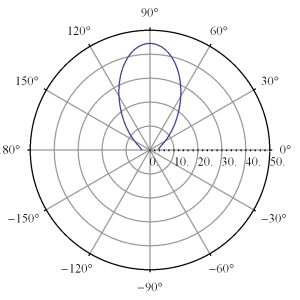
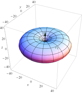
This array function is highly phase dependent, plotted for \( u_0 = 0 \) in fig. 1, and fig. 2.

ChebychevSecondMethodPolarFig3pn

fig 1. Plot with u_0 = 0, d = lambda/4

ChebychevSecondMethodSPolarFig4pn

fig 2. Spherical plot with u_0 = 0, d = lambda/4

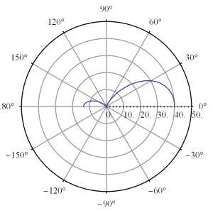
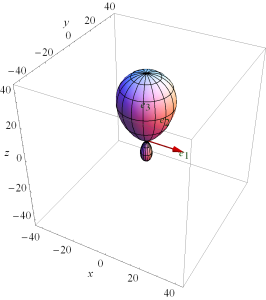
This can be directed along a single direction (z-axis) with higher phase choices as illustrated in fig. 3, and fig. 4.


ChebychevSecondMethodPolarFig1pn

fig 3. Plot with u_0 = 3.5, d = 0.4 lambda

ChebychevSecondMethodSPolarFig2pn

fig 4. Spherical plot with u_0 = 3.5, d = 0.4 lambda


These can be explored interactively in this Mathematica Manipulate panel.

References

[1] Constantine A Balanis. Antenna theory: analysis and design. John Wiley \& Sons, 3rd edition, 2005.