ece1229

Resolving fields into components parallel to the reflecting plane

March 6, 2015 ece1229 , , , , ,

[Click here for a PDF of this post with nicer formatting]

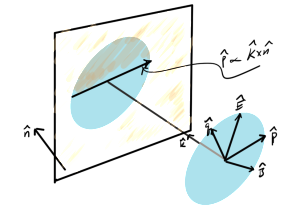
In order to apply the Fresnel equations, the field components have to be resolved into components where either the electric field or the magnetic field is parallel to the plane of reflection. The geometry of this, with the wave vector direction \( \kcap \) and the electric and magnetic field phasors perpendicular to that direction is sketched in fig. 1.

resolvingFieldsIncidentOnObliquePlaneFig1

fig. 1. Field components relative to reflecting plane


If the incident wave is a plane wave, or equivalently a far field spherical wave, it will have the form

\begin{equation}\label{eqn:resolvingFieldsIncidentOnPlane:20}
\BH = \inv{\mu_0} \kcap \cross \BE,
\end{equation}

with the field directions and wave vector directions satisfying

\begin{equation}\label{eqn:resolvingFieldsIncidentOnPlane:60}
\Ecap \cross \Hcap = \kcap
\end{equation}
\begin{equation}\label{eqn:resolvingFieldsIncidentOnPlane:80}
\Ecap \cdot \kcap = 0
\end{equation}
\begin{equation}\label{eqn:resolvingFieldsIncidentOnPlane:100}
\Hcap \cdot \kcap = 0.
\end{equation}

The key to resolving the fields into components parallel to the plane of reflection lies in the observation that the cross product of the plane normal \( \ncap \) and the incident wave vector direction \( \kcap \) lies in that plane. With

\begin{equation}\label{eqn:resolvingFieldsIncidentOnPlane:140}
\pcap = \frac{\kcap \cross \ncap}{\Abs{\kcap \cross \ncap}}
\end{equation}
\begin{equation}\label{eqn:resolvingFieldsIncidentOnPlane:160}
\qcap = \kcap \cross \pcap,
\end{equation}

the field directions can be resolved into components

\begin{equation}\label{eqn:resolvingFieldsIncidentOnPlane:200}
\BE = \lr{ \BE \cdot \pcap } \pcap + \lr{ \BE \cdot \qcap } \qcap = E_\parallel \pcap + E_\perp \qcap
\end{equation}
\begin{equation}\label{eqn:resolvingFieldsIncidentOnPlane:220}
\BH = \lr{ \BH \cdot \pcap } \pcap + \lr{ \BH \cdot \qcap } \qcap = H_\parallel \pcap + H_\perp \qcap.
\end{equation}

This subdivides the fields into two pairs, one with the electric field parallel to the reflection plane

\begin{equation}\label{eqn:resolvingFieldsIncidentOnPlane:240}
\begin{aligned}
\BE_1 &= \lr{ \BE \cdot \pcap } \pcap = E_\parallel \pcap \\
\BH_1 &= \lr{ \BH \cdot \qcap } \qcap = H_\perp \qcap,
\end{aligned}
\end{equation}

and one with the magnetic field parallel to the reflection plane

\begin{equation}\label{eqn:resolvingFieldsIncidentOnPlane:260}
\begin{aligned}
\BH_2 &= \lr{ \BH \cdot \pcap } \pcap = H_\parallel \pcap \\
\BE_2 &= \lr{ \BE \cdot \qcap } \qcap = E_\perp \qcap.
\end{aligned}
\end{equation}

This is most of what we need to proceed with the reflection and transmission analysis. The only task remaining is to determine the reflection angle.

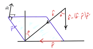
Using a pencil with the tip on the table I was able to convince myself by observation that there is always a normal plane of incidence regardless of any oblique angle that the ray hits the reflecting surface. This was, for some reason, not intuitively obvious to me. Having done that, the geometry must be reduced to what is sketched in fig. 2.

resolvingAngleOfIncidenceFig1

fig. 2. Angle of incidence determination


Once \( \pcap \) has been determined, regardless of it’s orientation in the reflection plane, the component of \( \kcap \) that is normal, directed towards, the plane of reflection is

\begin{equation}\label{eqn:resolvingFieldsIncidentOnPlane:280}
\kcap – \lr{ \kcap \cdot \pcap } \pcap,
\end{equation}

with (squared) length

\begin{equation}\label{eqn:resolvingFieldsIncidentOnPlane:300}
\begin{aligned}
\lr{ \kcap – \lr{ \kcap \cdot \pcap } \pcap }^2
&=
1 + \lr{ \kcap \cdot \pcap }^2 – 2 \lr{ \kcap \cdot \pcap }^2 \\
&=
1 – \lr{ \kcap \cdot \pcap }^2.
\end{aligned}
\end{equation}

The angle of incidence, relative to the normal to the reflection plane, follows from

\begin{equation}\label{eqn:resolvingFieldsIncidentOnPlane:320}
\begin{aligned}
\cos\theta
&= \kcap \cdot \frac{
\kcap – \lr{ \kcap \cdot \pcap } \pcap }{
\sqrt{
1 – \lr{ \kcap \cdot \pcap }^2
}
} \\
&=
\sqrt{
1 – \lr{ \kcap \cdot \pcap }^2
},
\end{aligned}
\end{equation}

Expanding the dot product above gives

\begin{equation}\label{eqn:resolvingFieldsIncidentOnPlane:360}
\begin{aligned}
\kcap \cdot \pcap’
&=
\kcap \cdot \lr{ \pcap \cross \ncap } \\
&=
\frac{1}{\Abs{\kcap \cross \ncap} } \kcap \cdot \lr{ \lr{\kcap \cross \ncap} \cross \ncap },
\end{aligned}
\end{equation}

where

\begin{equation}\label{eqn:resolvingFieldsIncidentOnPlane:380}
\begin{aligned}
\kcap \cdot \lr{ \lr{\kcap \cross \ncap} \cross \ncap }
&=
k_r \epsilon_{r s t} \lr{\kcap \cross \ncap}_s n_t \\
&=
k_r \epsilon_{r s t} \epsilon_{s a b} k_a n_b n_t \\
&=
-k_r \delta_{r t}^{[a b]} k_a n_b n_t \\
&=
-k_r n_t \lr{ k_r n_t – k_t n_r } \\
&=
-1 + \lr{ \kcap \cdot \ncap}^2.
\end{aligned}
\end{equation}

That gives

\begin{equation}\label{eqn:resolvingFieldsIncidentOnPlane:400}
\begin{aligned}
\kcap \cdot \pcap’
&=
\frac{-1 + \lr{ \kcap \cdot \ncap}^2}{\sqrt{1 – \lr{ \kcap \cdot \ncap}^2} } \\
&=
-\sqrt{1 – \lr{ \kcap \cdot \ncap}^2},
\end{aligned}
\end{equation}

or

\begin{equation}\label{eqn:resolvingFieldsIncidentOnPlane:420}
\begin{aligned}
\cos\theta
&= \sqrt{ 1 – \lr{-\sqrt{1 – \lr{ \kcap \cdot \ncap}^2}}^2 } \\
&= \sqrt{ \lr{ \kcap \cdot \ncap}^2 } \\
&= \kcap \cdot \ncap.
\end{aligned}
\end{equation}

This surprisingly simple result makes so much sense, it is an awful admission of stupidity that I went through all the vector algebra to get it instead of just writing it down directly.

The end result is the reflection angle is given by

\begin{equation}\label{eqn:resolvingFieldsIncidentOnPlane:340}
\boxed{
\theta = \cos^{-1} \kcap \cdot \ncap,
}
\end{equation}

where the reflection plane normal should off the back surface to get the sign right. The only detail left is the vector direction of the reflected ray (as well as the direction for the transmitted ray if that is of interest). The reflected ray direction flips the sign of the normal component of the ray

\begin{equation}\label{eqn:resolvingFieldsIncidentOnPlane:440}
\begin{aligned}
\kcap’
&= -\lr{\kcap \cdot \ncap} \ncap + \lr{ \kcap \wedge \ncap} \ncap \\
&= -\lr{\kcap \cdot \ncap} \ncap + \kcap – \lr{ \ncap \kcap} \cdot \ncap \\
&= \kcap -2 \lr{\kcap \cdot \ncap} \ncap.
\end{aligned}
\end{equation}

Here the sign of the normal doesn’t matter since it only occurs quadratically.

This now supplies everything needed for the application of the Fresnel equations to determine the reflected ray characteristics of an arbitrarily polarized incident field.
Duality transformation

March 2, 2015 ece1229 , , , , , ,

[Click here for a PDF of this post with nicer formatting]

In a discussion of Dirac’s monopoles, [1] introduces a duality transformation, forming electric and magnetic fields by forming a rotation that combines a different pair of electric and magnetic fields. In SI units that transformation becomes

\begin{equation}\label{eqn:dualityTransformation:40}
\begin{bmatrix}
\boldsymbol{\mathcal{E}} \\
\eta \boldsymbol{\mathcal{H}}
\end{bmatrix}
=
\begin{bmatrix}
\cos\theta & \sin\theta \\
-\sin\theta & \cos\theta
\end{bmatrix}
\begin{bmatrix}
\boldsymbol{\mathcal{E}}’ \\
\eta \boldsymbol{\mathcal{H}}’
\end{bmatrix}
\end{equation}
\begin{equation}\label{eqn:dualityTransformation:60}
\begin{bmatrix}
\boldsymbol{\mathcal{D}} \\
\boldsymbol{\mathcal{B}}/\eta
\end{bmatrix}
=
\begin{bmatrix}
\cos\theta & \sin\theta \\
-\sin\theta & \cos\theta
\end{bmatrix}
\begin{bmatrix}
\boldsymbol{\mathcal{D}}’ \\
\boldsymbol{\mathcal{B}}’/\eta
\end{bmatrix},
\end{equation}

where \( \eta = \sqrt{\mu_0/\epsilon_0} \). It is left as an exercise to the reader to show that application of these to Maxwell’s equations

\begin{equation}\label{eqn:dualityTransformation:100}
\spacegrad \cdot \boldsymbol{\mathcal{E}} = \rho_{\textrm{e}}/\epsilon_0
\end{equation}
\begin{equation}\label{eqn:dualityTransformation:120}
\spacegrad \cdot \boldsymbol{\mathcal{H}} = \rho_{\textrm{m}}/\mu_0
\end{equation}
\begin{equation}\label{eqn:dualityTransformation:140}
-\spacegrad \cross \boldsymbol{\mathcal{E}} – \partial_t \boldsymbol{\mathcal{B}} = \boldsymbol{\mathcal{J}}_{\textrm{m}}
\end{equation}
\begin{equation}\label{eqn:dualityTransformation:160}
\spacegrad \cross \boldsymbol{\mathcal{H}} – \partial_t \boldsymbol{\mathcal{D}} = \boldsymbol{\mathcal{J}}_{\textrm{e}},
\end{equation}

determine a similar relation between the sources. That transformation of Maxwell’s equation is

\begin{equation}\label{eqn:dualityTransformation:200}
\spacegrad \cdot \lr{ \cos\theta \boldsymbol{\mathcal{E}}’ + \sin\theta \eta \boldsymbol{\mathcal{H}}’ } = \rho_{\textrm{e}}/\epsilon_0
\end{equation}
\begin{equation}\label{eqn:dualityTransformation:220}
\spacegrad \cdot \lr{ -\sin\theta \boldsymbol{\mathcal{E}}’/\eta + \cos\theta \boldsymbol{\mathcal{H}}’ } = \rho_{\textrm{m}}/\mu_0
\end{equation}
\begin{equation}\label{eqn:dualityTransformation:240}
-\spacegrad \cross \lr{ \cos\theta \boldsymbol{\mathcal{E}}’ + \sin\theta \eta \boldsymbol{\mathcal{H}}’ } – \partial_t \lr{ – \sin\theta \eta \boldsymbol{\mathcal{D}}’ + \cos\theta \boldsymbol{\mathcal{B}}’ } = \boldsymbol{\mathcal{J}}_{\textrm{m}}
\end{equation}
\begin{equation}\label{eqn:dualityTransformation:260}
\spacegrad \cross \lr{ -\sin\theta \boldsymbol{\mathcal{E}}’/\eta + \cos\theta \boldsymbol{\mathcal{H}}’ } – \partial_t \lr{ \cos\theta \boldsymbol{\mathcal{D}}’ + \sin\theta \boldsymbol{\mathcal{B}}’/\eta } = \boldsymbol{\mathcal{J}}_{\textrm{e}}.
\end{equation}

A bit of rearranging gives

\begin{equation}\label{eqn:dualityTransformation:400}
\begin{bmatrix}
\eta \rho_{\textrm{e}} \\
\rho_{\textrm{m}}
\end{bmatrix}
=
\begin{bmatrix}
\cos\theta & \sin\theta \\
-\sin\theta & \cos\theta
\end{bmatrix}
\begin{bmatrix}
\eta \rho_{\textrm{e}}’ \\
\rho_{\textrm{m}}’
\end{bmatrix}
\end{equation}
\begin{equation}\label{eqn:dualityTransformation:420}
\begin{bmatrix}
\eta \boldsymbol{\mathcal{J}}_{\textrm{e}} \\
\boldsymbol{\mathcal{J}}_{\textrm{m}} \\
\end{bmatrix}
=
\begin{bmatrix}
\cos\theta & \sin\theta \\
-\sin\theta & \cos\theta
\end{bmatrix}
\begin{bmatrix}
\eta \boldsymbol{\mathcal{J}}_{\textrm{e}}’ \\
\boldsymbol{\mathcal{J}}_{\textrm{m}}’ \\
\end{bmatrix}.
\end{equation}

For example, with \( \rho_{\textrm{m}} = \boldsymbol{\mathcal{J}}_{\textrm{m}} = 0 \), and \( \theta = \pi/2 \), the transformation of sources is

\begin{equation}\label{eqn:dualityTransformation:440}
\begin{aligned}
\rho_{\textrm{e}}’ &= 0 \\
\boldsymbol{\mathcal{J}}_{\textrm{e}}’ &= 0 \\
\rho_{\textrm{m}}’ &= \eta \rho_{\textrm{e}} \\
\boldsymbol{\mathcal{J}}_{\textrm{m}}’ &= \eta \boldsymbol{\mathcal{J}}_{\textrm{e}},
\end{aligned}
\end{equation}

and Maxwell’s equations then have only magnetic sources

\begin{equation}\label{eqn:dualityTransformation:480}
\spacegrad \cdot \boldsymbol{\mathcal{E}}’ = 0
\end{equation}
\begin{equation}\label{eqn:dualityTransformation:500}
\spacegrad \cdot \boldsymbol{\mathcal{H}}’ = \rho_{\textrm{m}}’/\mu_0
\end{equation}
\begin{equation}\label{eqn:dualityTransformation:520}
-\spacegrad \cross \boldsymbol{\mathcal{E}}’ – \partial_t \boldsymbol{\mathcal{B}}’ = \boldsymbol{\mathcal{J}}_{\textrm{m}}’
\end{equation}
\begin{equation}\label{eqn:dualityTransformation:540}
\spacegrad \cross \boldsymbol{\mathcal{H}}’ – \partial_t \boldsymbol{\mathcal{D}}’ = 0.
\end{equation}

Of this relation Jackson points out that “The invariance of the equations of electrodynamics under duality transformations shows that it is a matter of convention to speak of a particle possessing an electric charge, but not magnetic charge.” This is an interesting comment, and worth some additional thought.

References

[1] JD Jackson. Classical Electrodynamics. John Wiley and Sons, 2nd edition, 1975.

Duality transformation of the far field fields.

February 27, 2015 ece1229 , , , ,

We’ve seen that the far field electric and magnetic fields associated with a magnetic vector potential were

\begin{equation}\label{eqn:dualFarField:40}
\BE = -j \omega \textrm{Proj}_\T \BA,
\end{equation}
\begin{equation}\label{eqn:dualFarField:60}
\BH = \inv{\eta} \kcap \cross \BE.
\end{equation}

It’s worth a quick note that the duality transformation for this, referring to [1] tab. 3.2, is

\begin{equation}\label{eqn:dualFarField:100}
\BH = -j \omega \textrm{Proj}_\T \BF
\end{equation}
\begin{equation}\label{eqn:dualFarField:120}
\BE = -\eta \kcap \cross \BH.
\end{equation}

What does \( \BH \) look like in terms of \( \BA \), and \( \BE \) look like in terms of \( \BH \)?

The first is

\begin{equation}\label{eqn:dualFarField:140}
\BH
= -\frac{j \omega}{\eta} \kcap \cross \lr{ \BA – \lr{\BA \cdot \kcap} \kcap },
\end{equation}

in which the \( \kcap \) crossed terms are killed, leaving

\begin{equation}\label{eqn:dualFarField:160}
\BH
= -\frac{j \omega}{\eta} \kcap \cross \BA.
\end{equation}

The electric field follows again using a duality transformation, so in terms of the electric vector potential, is

\begin{equation}\label{eqn:dualFarField:180}
\BE = j \omega \eta \kcap \cross \BF.
\end{equation}

These show explicitly that neither the electric or magnetic far field have any radial component, matching with intuition for transverse propagation of the fields.

References

[1] Constantine A Balanis. Antenna theory: analysis and design. John Wiley & Sons, 3rd edition, 2005.

Maxwell’s equations in tensor form with magnetic sources

February 22, 2015 ece1229 , , , , , , , , , , , , , , , , , , , , , , , , ,

[Click here for a PDF of this post with nicer formatting]

Following the principle that one should always relate new formalisms to things previously learned, I’d like to know what Maxwell’s equations look like in tensor form when magnetic sources are included. As a verification that the previous Geometric Algebra form of Maxwell’s equation that includes magnetic sources is correct, I’ll start with the GA form of Maxwell’s equation, find the tensor form, and then verify that the vector form of Maxwell’s equations can be recovered from the tensor form.

Tensor form

With four-vector potential \( A \), and bivector electromagnetic field \( F = \grad \wedge A \), the GA form of Maxwell’s equation is

\begin{equation}\label{eqn:gaMagneticSourcesToTensorToVector:20}
\grad F = \frac{J}{\epsilon_0 c} + M I.
\end{equation}

The left hand side can be unpacked into vector and trivector terms \( \grad F = \grad \cdot F + \grad \wedge F \), which happens to also separate the sources nicely as a side effect

\begin{equation}\label{eqn:gaMagneticSourcesToTensorToVector:60}
\grad \cdot F = \frac{J}{\epsilon_0 c}
\end{equation}
\begin{equation}\label{eqn:gaMagneticSourcesToTensorToVector:80}
\grad \wedge F = M I.
\end{equation}

The electric source equation can be unpacked into tensor form by dotting with the four vector basis vectors. With the usual definition \( F^{\alpha \beta} = \partial^\alpha A^\beta – \partial^\beta A^\alpha \), that is

\begin{equation}\label{eqn:gaMagneticSourcesToTensorToVector:100}
\begin{aligned}
\gamma^\mu \cdot \lr{ \grad \cdot F }
&=
\gamma^\mu \cdot \lr{ \grad \cdot \lr{ \grad \wedge A } } \\
&=
\gamma^\mu \cdot \lr{ \gamma^\nu \partial_\nu \cdot
\lr{ \gamma_\alpha \partial^\alpha \wedge \gamma_\beta A^\beta } } \\
&=
\gamma^\mu \cdot \lr{ \gamma^\nu \cdot \lr{ \gamma_\alpha \wedge \gamma_\beta
} } \partial_\nu \partial^\alpha A^\beta \\
&=
\inv{2}
\gamma^\mu \cdot \lr{ \gamma^\nu \cdot \lr{ \gamma_\alpha \wedge \gamma_\beta } }
\partial_\nu F^{\alpha \beta} \\
&=
\inv{2} \delta^{\nu \mu}_{[\alpha \beta]} \partial_\nu F^{\alpha \beta} \\
&=
\inv{2} \partial_\nu F^{\nu \mu}

\inv{2} \partial_\nu F^{\mu \nu} \\
&=
\partial_\nu F^{\nu \mu}.
\end{aligned}
\end{equation}

So the first tensor equation is

\begin{equation}\label{eqn:gaMagneticSourcesToTensorToVector:120}
\boxed{
\partial_\nu F^{\nu \mu} = \inv{c \epsilon_0} J^\mu.
}
\end{equation}

To unpack the magnetic source portion of Maxwell’s equation, put it first into dual form, so that it has four vectors on each side

\begin{equation}\label{eqn:gaMagneticSourcesToTensorToVector:140}
\begin{aligned}
M
&= – \lr{ \grad \wedge F} I \\
&= -\frac{1}{2} \lr{ \grad F + F \grad } I \\
&= -\frac{1}{2} \lr{ \grad F I – F I \grad } \\
&= – \grad \cdot \lr{ F I }.
\end{aligned}
\end{equation}

Dotting with \( \gamma^\mu \) gives

\begin{equation}\label{eqn:gaMagneticSourcesToTensorToVector:160}
\begin{aligned}
M^\mu
&= \gamma^\mu \cdot \lr{ \grad \cdot \lr{ – F I } } \\
&= \gamma^\mu \cdot \lr{ \gamma^\nu \partial_\nu \cdot \lr{ -\frac{1}{2}
\gamma^\alpha \wedge \gamma^\beta I F_{\alpha \beta} } } \\
&= -\inv{2}
\gpgradezero{
\gamma^\mu \cdot \lr{ \gamma^\nu \cdot \lr{ \gamma^\alpha \wedge \gamma^\beta I } }
}
\partial_\nu F_{\alpha \beta}.
\end{aligned}
\end{equation}

This scalar grade selection is a complete antisymmetrization of the indexes

\begin{equation}\label{eqn:gaMagneticSourcesToTensorToVector:180}
\begin{aligned}
\gpgradezero{
\gamma^\mu \cdot \lr{ \gamma^\nu \cdot \lr{ \gamma^\alpha \wedge \gamma^\beta I } }
}
&=
\gpgradezero{
\gamma^\mu \cdot \lr{ \gamma^\nu \cdot \lr{
\gamma^\alpha \gamma^\beta
\gamma_0 \gamma_1 \gamma_2 \gamma_3
} }
} \\
&=
\gpgradezero{
\gamma_0 \gamma_1 \gamma_2 \gamma_3
\gamma^\mu \gamma^\nu \gamma^\alpha \gamma^\beta
} \\
&=
\delta^{\mu \nu \alpha \beta}_{3 2 1 0} \\
&=
\epsilon^{\mu \nu \alpha \beta },
\end{aligned}
\end{equation}

so the magnetic source portion of Maxwell’s equation, in tensor form, is

\begin{equation}\label{eqn:gaMagneticSourcesToTensorToVector:200}
\boxed{
\inv{2} \epsilon^{\nu \alpha \beta \mu}
\partial_\nu F_{\alpha \beta}
=
M^\mu.
}
\end{equation}

Relating the tensor to the fields

The electromagnetic field has been identified with the electric and magnetic fields by

\begin{equation}\label{eqn:gaMagneticSourcesToTensorToVector:220}
F = \boldsymbol{\mathcal{E}} + c \mu_0 \boldsymbol{\mathcal{H}} I ,
\end{equation}

or in coordinates

\begin{equation}\label{eqn:gaMagneticSourcesToTensorToVector:240}
\inv{2} \gamma_\mu \wedge \gamma_\nu F^{\mu \nu}
= E^a \gamma_a \gamma_0 + c \mu_0 H^a \gamma_a \gamma_0 I.
\end{equation}

By forming the dot product sequence \( F^{\alpha \beta} = \gamma^\beta \cdot \lr{ \gamma^\alpha \cdot F } \), the electric and magnetic field components can be related to the tensor components. The electric field components follow by inspection and are

\begin{equation}\label{eqn:gaMagneticSourcesToTensorToVector:260}
E^b = \gamma^0 \cdot \lr{ \gamma^b \cdot F } = F^{b 0}.
\end{equation}

The magnetic field relation to the tensor components follow from

\begin{equation}\label{eqn:gaMagneticSourcesToTensorToVector:280}
\begin{aligned}
F^{r s}
&= F_{r s} \\
&= \gamma_s \cdot \lr{ \gamma_r \cdot \lr{ c \mu_0 H^a \gamma_a \gamma_0 I
} } \\
&=
c \mu_0 H^a \gpgradezero{ \gamma_s \gamma_r \gamma_a \gamma_0 I } \\
&=
c \mu_0 H^a \gpgradezero{ -\gamma^0 \gamma^1 \gamma^2 \gamma^3
\gamma_s \gamma_r \gamma_a \gamma_0 } \\
&=
c \mu_0 H^a \gpgradezero{ -\gamma^1 \gamma^2 \gamma^3
\gamma_s \gamma_r \gamma_a } \\
&=
– c \mu_0 H^a \delta^{[3 2 1]}_{s r a} \\
&=
c \mu_0 H^a \epsilon_{ s r a }.
\end{aligned}
\end{equation}

Expanding this for each pair of spacelike coordinates gives

\begin{equation}\label{eqn:gaMagneticSourcesToTensorToVector:320}
F^{1 2} = c \mu_0 H^3 \epsilon_{ 2 1 3 } = – c \mu_0 H^3
\end{equation}
\begin{equation}\label{eqn:gaMagneticSourcesToTensorToVector:340}
F^{2 3} = c \mu_0 H^1 \epsilon_{ 3 2 1 } = – c \mu_0 H^1
\end{equation}
\begin{equation}\label{eqn:gaMagneticSourcesToTensorToVector:360}
F^{3 1} = c \mu_0 H^2 \epsilon_{ 1 3 2 } = – c \mu_0 H^2,
\end{equation}

or

\begin{equation}\label{eqn:gaMagneticSourcesToTensorToVector:380}
\boxed{
\begin{aligned}
E^1 &= F^{1 0} \\
E^2 &= F^{2 0} \\
E^3 &= F^{3 0} \\
H^1 &= -\inv{c \mu_0} F^{2 3} \\
H^2 &= -\inv{c \mu_0} F^{3 1} \\
H^3 &= -\inv{c \mu_0} F^{1 2}.
\end{aligned}
}
\end{equation}

Recover the vector equations from the tensor equations

Starting with the non-dual Maxwell tensor equation, expanding the timelike index gives

\begin{equation}\label{eqn:gaMagneticSourcesToTensorToVector:480}
\begin{aligned}
\inv{c \epsilon_0} J^0
&= \inv{\epsilon_0} \rho \\
&=
\partial_\nu F^{\nu 0} \\
&=
\partial_1 F^{1 0}
+\partial_2 F^{2 0}
+\partial_3 F^{3 0}
\end{aligned}
\end{equation}

This is Gauss’s law

\begin{equation}\label{eqn:gaMagneticSourcesToTensorToVector:500}
\boxed{
\spacegrad \cdot \boldsymbol{\mathcal{E}}
=
\rho/\epsilon_0.
}
\end{equation}

For a spacelike index, any one is representive. Expanding index 1 gives

\begin{equation}\label{eqn:gaMagneticSourcesToTensorToVector:520}
\begin{aligned}
\inv{c \epsilon_0} J^1
&= \partial_\nu F^{\nu 1} \\
&= \inv{c} \partial_t F^{0 1}
+ \partial_2 F^{2 1}
+ \partial_3 F^{3 1} \\
&= -\inv{c} E^1
+ \partial_2 (c \mu_0 H^3)
+ \partial_3 (-c \mu_0 H^2) \\
&=
\lr{ -\inv{c} \PD{t}{\boldsymbol{\mathcal{E}}} + c \mu_0 \spacegrad \cross \boldsymbol{\mathcal{H}} } \cdot \Be_1.
\end{aligned}
\end{equation}

Extending this to the other indexes and multiplying through by \( \epsilon_0 c \) recovers the Ampere-Maxwell equation (assuming linear media)

\begin{equation}\label{eqn:gaMagneticSourcesToTensorToVector:540}
\boxed{
\spacegrad \cross \boldsymbol{\mathcal{H}} = \boldsymbol{\mathcal{J}} + \PD{t}{\boldsymbol{\mathcal{D}}}.
}
\end{equation}

The expansion of the 0th free (timelike) index of the dual Maxwell tensor equation is

\begin{equation}\label{eqn:gaMagneticSourcesToTensorToVector:400}
\begin{aligned}
M^0
&=
\inv{2} \epsilon^{\nu \alpha \beta 0}
\partial_\nu F_{\alpha \beta} \\
&=
-\inv{2} \epsilon^{0 \nu \alpha \beta}
\partial_\nu F_{\alpha \beta} \\
&=
-\inv{2}
\lr{
\partial_1 (F_{2 3} – F_{3 2})
+\partial_2 (F_{3 1} – F_{1 3})
+\partial_3 (F_{1 2} – F_{2 1})
} \\
&=

\lr{
\partial_1 F_{2 3}
+\partial_2 F_{3 1}
+\partial_3 F_{1 2}
} \\
&=

\lr{
\partial_1 (- c \mu_0 H^1 ) +
\partial_2 (- c \mu_0 H^2 ) +
\partial_3 (- c \mu_0 H^3 )
},
\end{aligned}
\end{equation}

but \( M^0 = c \rho_m \), giving us Gauss’s law for magnetism (with magnetic charge density included)

\begin{equation}\label{eqn:gaMagneticSourcesToTensorToVector:420}
\boxed{
\spacegrad \cdot \boldsymbol{\mathcal{H}} = \rho_m/\mu_0.
}
\end{equation}

For the spacelike indexes of the dual Maxwell equation, only one need be computed (say 1), and cyclic permutation will provide the rest. That is

\begin{equation}\label{eqn:gaMagneticSourcesToTensorToVector:440}
\begin{aligned}
M^1
&= \inv{2} \epsilon^{\nu \alpha \beta 1} \partial_\nu F_{\alpha \beta} \\
&=
\inv{2} \lr{ \partial_2 \lr{F_{3 0} – F_{0 3}} }
+\inv{2} \lr{ \partial_3 \lr{F_{0 2} – F_{0 2}} }
+\inv{2} \lr{ \partial_0 \lr{F_{2 3} – F_{3 2}} } \\
&=
– \partial_2 F^{3 0}
+ \partial_3 F^{2 0}
+ \partial_0 F_{2 3} \\
&=
-\partial_2 E^3 + \partial_3 E^2 + \inv{c} \PD{t}{} \lr{ – c \mu_0 H^1 } \\
&= – \lr{ \spacegrad \cross \boldsymbol{\mathcal{E}} + \mu_0 \PD{t}{\boldsymbol{\mathcal{H}}} } \cdot \Be_1.
\end{aligned}
\end{equation}

Extending this to the rest of the coordinates gives the Maxwell-Faraday equation (as extended to include magnetic current density sources)

\begin{equation}\label{eqn:gaMagneticSourcesToTensorToVector:460}
\boxed{
\spacegrad \cross \boldsymbol{\mathcal{E}} = -\boldsymbol{\mathcal{M}} – \mu_0 \PD{t}{\boldsymbol{\mathcal{H}}}.
}
\end{equation}

This takes things full circle, going from the vector differential Maxwell’s equations, to the Geometric Algebra form of Maxwell’s equation, to Maxwell’s equations in tensor form, and back to the vector form. Not only is the tensor form of Maxwell’s equations with magnetic sources now known, the translation from the tensor and vector formalism has also been verified, and miraculously no signs or factors of 2 were lost or gained in the process.

Energy momentum conservation with magnetic sources. Comparison to frequency domain and reciprocity theorem.

February 20, 2015 ece1229 , , ,

[Click here for a PDF of this post with nicer formatting]

In the frequency domain

In the frequency domain with \( \boldsymbol{\mathcal{E}} = \textrm{Re} \BE e^{j \omega t}, \boldsymbol{\mathcal{H}} = \textrm{Re} \BH e^{j \omega t} \). Using the electric field dot product as an example, note that we can write

\begin{equation}\label{eqn:energyMomentumWithMagneticSources:480}
\boldsymbol{\mathcal{E}} = \inv{2} \lr{ \BE e^{j \omega t} + \BE^\conj e^{-j \omega t} },
\end{equation}

so

\begin{equation}\label{eqn:energyMomentumWithMagneticSources:500}
\begin{aligned}
\boldsymbol{\mathcal{E}}^2
&=
\inv{2} \lr{ \BE e^{j \omega t} + \BE^\conj e^{-j \omega t} }
\cdot
\inv{2} \lr{ \BE e^{j \omega t} + \BE^\conj e^{-j \omega t} } \\
&=
\inv{4} \lr{
\BE^2 e^{2 j \omega t}
+ \BE \cdot \BE^\conj + \BE^\conj \cdot \BE
+\lr{\BE^\conj}^2 e^{-2 j \omega t}
} \\
&=
\inv{2} \textrm{Re}
\lr{
\BE \cdot \BE^\conj
+
\BE^2 e^{2 j \omega t}
}.
\end{aligned}
\end{equation}

Similarly, for the cross product

\begin{equation}\label{eqn:energyMomentumWithMagneticSources:540}
\begin{aligned}
\boldsymbol{\mathcal{E}} \cross \boldsymbol{\mathcal{H}}
&=
\inv{4}
\lr{
\BE \cross \BH e^{2 j \omega t}
+ \BE \cross \BH^\conj + \BE^\conj \cross \BH
+ \lr{ \BE^\conj \cross \BH^\conj } e^{-2 j \omega t}
} \\
&=
\inv{2}
\textrm{Re}
\lr{
\BE \cross \BH^\conj
+
\BE \cross \BH e^{2 j \omega t}
}.
\end{aligned}
\end{equation}

Given phasor representations of the sources \( \boldsymbol{\mathcal{M}} = \BM e^{j \omega t}, \boldsymbol{\mathcal{J}} = \BJ e^{j \omega t} \), \ref{eqn:energyMomentumWithMagneticSources:40} can be recast into (a messy) phasor form

\begin{equation}\label{eqn:energyMomentumWithMagneticSources:560}
\begin{aligned}
\inv{2} &\textrm{Re} \inv{2} \PD{t}{} \lr{
\epsilon_0 \BE \cdot \BE^\conj
+ \mu_0 \BH \cdot \BH^\conj
+ \epsilon_0 \BE^2 e^{ 2 j \omega t}
+ \mu_0 \BH^2 e^{ 2 j \omega t}
} \\
&+
\inv{2} \textrm{Re} \spacegrad \cdot \lr{
\BE \cross \BH^\conj
+\BE \cross \BH e^{ 2 j \omega t}
} \\
&=
\inv{2} \textrm{Re}
\lr{
– \BH \cdot \BM^\conj
– \BE \cdot \BJ^\conj
– \BH \cdot \BM e^{2 j \omega t}
– \BE \cdot \BJ e^{2 j \omega t}
}.
\end{aligned}
\end{equation}

In particular, when averaged over one period, the oscillatory terms vanish. The time averaged equivalent of the Poynting theorem is thus

\begin{equation}\label{eqn:energyMomentumWithMagneticSources:580}
0 =
{\left[
\textrm{Re}
\lr{
\inv{2} \PD{t}{} \lr{
\epsilon_0 \BE \cdot \BE^\conj
+ \mu_0 \BH \cdot \BH^\conj
}
+
\spacegrad \cdot \lr{
\BE \cross \BH^\conj
}
+
\BH \cdot \BM^\conj
+
\BE \cdot \BJ^\conj
}
\right]
}_{\textrm{av}}.
\end{equation}

Comparison to the reciprocity theorem result

The reciprocity theorem had a striking similarity to the Poynting theorem above, which isn’t suprising since both were derived by calculating the divergence of a Poynting like quantity.

Here’s a repetition of the reciprocity divergence calculation without the single frequency (phasor) assumption

\begin{equation}\label{eqn:energyMomentumWithMagneticSources:600}
\begin{aligned}
\spacegrad \cdot &\lr{
\boldsymbol{\mathcal{E}}^{(a)} \cross \boldsymbol{\mathcal{H}}^{(b)}
-\boldsymbol{\mathcal{E}}^{(b)} \cross \boldsymbol{\mathcal{H}}^{(a)}
} \\
&=
\boldsymbol{\mathcal{H}}^{(b)} \cdot \lr{ \spacegrad \cross \boldsymbol{\mathcal{E}}^{(a)} } -\boldsymbol{\mathcal{E}}^{(a)} \cdot \lr{ \spacegrad \cross \boldsymbol{\mathcal{H}}^{(b)} } \\
&\quad
-\boldsymbol{\mathcal{H}}^{(a)} \cdot \lr{ \spacegrad \cross \boldsymbol{\mathcal{E}}^{(b)} } +\boldsymbol{\mathcal{E}}^{(b)} \cdot \lr{ \spacegrad \cross \boldsymbol{\mathcal{H}}^{(a)} } \\
&=
-\boldsymbol{\mathcal{H}}^{(b)} \cdot \lr{ \mu_0 \partial_t \boldsymbol{\mathcal{H}}^{(a)} + \boldsymbol{\mathcal{M}}^{(a)} }
-\boldsymbol{\mathcal{E}}^{(a)} \cdot \lr{ \boldsymbol{\mathcal{J}}^{(b)} + \epsilon_0 \partial_t \boldsymbol{\mathcal{E}}^{(b)} } \\
&\quad
+\boldsymbol{\mathcal{H}}^{(a)} \cdot \lr{ \mu_0 \partial_t \boldsymbol{\mathcal{H}}^{(b)} + \boldsymbol{\mathcal{M}}^{(b)} }
+\boldsymbol{\mathcal{E}}^{(b)} \cdot \lr{ \boldsymbol{\mathcal{J}}^{(a)} + \epsilon_0 \partial_t \boldsymbol{\mathcal{E}}^{(a)} } \\
&=
\epsilon_0
\lr{
\boldsymbol{\mathcal{E}}^{(b)} \cdot \partial_t \boldsymbol{\mathcal{E}}^{(a)}
-\boldsymbol{\mathcal{E}}^{(a)} \cdot \partial_t \boldsymbol{\mathcal{E}}^{(b)}
}
+
\mu_0
\lr{
\boldsymbol{\mathcal{H}}^{(a)} \cdot \partial_t \boldsymbol{\mathcal{H}}^{(b)}
-\boldsymbol{\mathcal{H}}^{(b)} \cdot \partial_t \boldsymbol{\mathcal{H}}^{(a)}
} \\
&+\boldsymbol{\mathcal{H}}^{(a)} \cdot \boldsymbol{\mathcal{M}}^{(b)}
-\boldsymbol{\mathcal{H}}^{(b)} \cdot \boldsymbol{\mathcal{M}}^{(a)}
+\boldsymbol{\mathcal{E}}^{(b)} \cdot \boldsymbol{\mathcal{J}}^{(a)}
-\boldsymbol{\mathcal{E}}^{(a)} \cdot \boldsymbol{\mathcal{J}}^{(b)}
\end{aligned}
\end{equation}

What do these time derivative terms look like in the frequency domain?

\begin{equation}\label{eqn:energyMomentumWithMagneticSources:620}
\begin{aligned}
\boldsymbol{\mathcal{E}}^{(b)} \cdot \partial_t \boldsymbol{\mathcal{E}}^{(a)}
&=
\inv{4}
\lr{
\BE^{(b)} e^{j \omega t}
+
{\BE^{(b)}}^\conj e^{-j \omega t}
}
\cdot
\partial_t
\lr{
\BE^{(a)} e^{j \omega t}
+
{\BE^{(a)}}^\conj e^{-j \omega t}
} \\
&=
\frac{j \omega}{4}
\lr{
\BE^{(b)} e^{j \omega t}
+
{\BE^{(b)}}^\conj e^{-j \omega t}
}
\cdot
\lr{
\BE^{(a)} e^{j \omega t}

{\BE^{(a)}}^\conj e^{-j \omega t}
} \\
&=
\frac{\omega}{4}
\lr{
j \BE^{(a)} \cdot { \BE^{(b)} }^\conj
-j \BE^{(b)} \cdot { \BE^{(a)} }^\conj
+j \BE^{(a)} \cdot \BE^{(b)} e^{ 2 j \omega t }
-j { \BE^{(a)}}^\conj \cdot { \BE^{(b)} }^\conj e^{ -2 j \omega t }
} \\
&=
\inv{2} \textrm{Re}
\lr{
j \omega \BE^{(a)} \cdot { \BE^{(b)} }^\conj
+ j \omega \BE^{(a)} \cdot \BE^{(b)} e^{ 2 j \omega t }
}
\end{aligned}
\end{equation}

Taking the difference,

\begin{equation}\label{eqn:energyMomentumWithMagneticSources:640}
\begin{aligned}
\boldsymbol{\mathcal{E}}^{(b)} \cdot \partial_t \boldsymbol{\mathcal{E}}^{(a)}
-\boldsymbol{\mathcal{E}}^{(a)} \cdot \partial_t \boldsymbol{\mathcal{E}}^{(b)}
&=
\inv{2} \textrm{Re}
\lr{
j \omega \BE^{(a)} \cdot { \BE^{(b)} }^\conj
– j \omega \BE^{(b)} \cdot { \BE^{(a)} }^\conj
+ j \omega \BE^{(a)} \cdot \BE^{(b)} e^{ 2 j \omega t }
– j \omega \BE^{(b)} \cdot \BE^{(a)} e^{ 2 j \omega t }
} \\
&=
– \omega \textrm{Im}
\lr{
\BE^{(a)} \cdot { \BE^{(b)} }^\conj
+ \BE^{(a)} \cdot \BE^{(b)} e^{ 2 j \omega t }
},
\end{aligned}
\end{equation}

so we have

\begin{equation}\label{eqn:energyMomentumWithMagneticSources:660}
0
=
{
\left[
\spacegrad \cdot \textrm{Re} \lr{
\BE^{(a)} \cross {\BH^{(b)}}^\conj
-\BE^{(b)} \cross {\BH^{(a)}}^\conj
}
+
\omega \textrm{Im}
\lr{
\epsilon_0
\BE^{(a)} \cdot { \BE^{(b)} }^\conj
+
\mu_0
\BH^{(a)} \cdot { \BH^{(b)} }^\conj
}
+ \textrm{Re}
\lr{
-\BH^{(a)} \cdot { \BM^{(b)} }^\conj
+\BH^{(b)} \cdot { \BM^{(a)} }^\conj
-\BE^{(b)} \cdot { \BJ^{(a)} }^\conj
+\BE^{(a)} \cdot { \BJ^{(b)} }^\conj
}
\right]
}_{\textrm{av}}.
\end{equation}

Observe that the perfect cancellation of the time derivative terms only occurs when the cross product differences were those of the phasors. When those cross differences are those of the actual fields, like those in the Poynting theorem, there is a frequency dependent term is that expansion.