math and physics play

Circumference of an ellipse

March 9, 2015 math and physics play , , , ,

[Click here for a PDF of this post with nicer formatting]

Motivation

Lance told me they’ve been covering the circumference of a circle in school this week. This made me think of the generalization of a circle, the ellipse, but I couldn’t recall what the circumference of an ellipse was. Sofia guessed \( \pi ( a + b ) \). Her reasoning was that this goes to \( 2 \pi r \) when the ellipse is circular, just like the area of an ellipse \( \pi a b \), goes to \( \pi a^2 \) in the circular limit. That seemed reasonable to me, but also strange since I didn’t recall any \( \pi ( a + b ) \) formula.

It turns out that there’s no closed form expression for the circumference of an ellipse, unless you count infinite series or special functions. Here I’ll calculate one expression for this circumference.

Geometry recap

There’s two ways that I think of ellipses. One is the shape that you get when you put a couple tacks in a paper, and use a string and pencil to trace it out, as sketched in fig. 1.
The other is the basic vector parameterization of that same path

\begin{equation}\label{eqn:elipticCircumference:20}
\Br = ( a \cos\theta, b \sin\theta ).
\end{equation}

ellipseFig1

fig. 1. Ellipse, showing tracing curve from the foci.


It’s been a long time since grade 11 when I would have taken it for granted that these two representations are identical. To do so, we’d have to know where the foci of the ellipse sit. Cheating a bit I find in [1] that the foci are located at

\begin{equation}\label{eqn:elipticCircumference:40}
\Bf_{\pm} = \pm \sqrt{ a^2 – b^2 } (1, 0).
\end{equation}

This and the equivalence of the pencil and tack representation of the ellipse can be verified by checking that the “length of the string” equals \( 2 a \) as expected.

That string length is

\begin{equation}\label{eqn:elipticCircumference:60}
\begin{aligned}
\Abs{ \Br – \Bf_{+} } + \Abs{ \Br – \Bf_{-} }
&=
\sqrt{ (a \cos\theta – f)^2 + b^2 \sin^2\theta }
+
\sqrt{ (a \cos\theta + f)^2 + b^2 \sin^2\theta } \\
&=
\sqrt{ a^2 \cos^2 \theta + f^2 – 2 a f \cos\theta + b^2 \lr{ 1 – \cos^2\theta } } \\
&\quad +
\sqrt{ a^2 \cos^2 \theta + f^2 + 2 a f \cos\theta + b^2 \lr{ 1 – \cos^2\theta } }.
\end{aligned}
\end{equation}

These square roots simplify nicely

\begin{equation}\label{eqn:elipticCircumference:80}
\begin{aligned}
\sqrt{ a^2 \cos^2 \theta + f^2 \pm 2 a f \cos\theta + b^2 \lr{ 1 – \cos^2\theta } }
&=
\sqrt{ (a^2 – b^2) \cos^2 \theta + a^2 – b^2 \pm 2 a f \cos\theta + b^2 } \\
&=
\sqrt{ f^2 \cos^2 \theta + a^2 \pm 2 a f \cos\theta } \\
&=
\sqrt{ (a \pm f \cos\theta)^2 } \\
&=
a \pm f \cos\theta.
\end{aligned}
\end{equation}

So the total length from one focus to a point on the ellipse, back to the other focus, is

\begin{equation}\label{eqn:elipticCircumference:100}
\Abs{ \Br – \Bf_{+} } + \Abs{ \Br – \Bf_{-} }
=
a + f \cos\theta + a – f \cos\theta = 2 a,
\end{equation}

as expected. That verifies that the trigonometric parameterization matches with the pencil and tacks representation of an ellipse (provided the foci are placed at the points \ref{eqn:elipticCircumference:40}).

Calculating the circumference

The circumference expression can almost be written by inspection. An element of the tangent vector along the curve is

\begin{equation}\label{eqn:elipticCircumference:340}
\frac{d\Br}{d\theta} = ( -a \sin\theta, b \cos\theta ),
\end{equation}

so the circumference is just a one liner

\begin{equation}\label{eqn:elipticCircumference:280}
C = 4 \int_0^{\pi/2} \sqrt{ a^2 \sin^2\theta + b^2 \cos^2 \theta} d\theta.
\end{equation}

The problem is that this one liner isn’t easy to evaluate. The square root can be put in a slightly simpler form in terms of the eccentricity, which is defined by

\begin{equation}\label{eqn:elipticCircumference:300}
e = \frac{f}{a} = \frac{\sqrt{a^2 – b^2}}{a} = \sqrt{ 1 – \frac{b^2}{a^2} }.
\end{equation}

Factoring out \( a \) and writing the sine as a cosine gives

\begin{equation}\label{eqn:elipticCircumference:320}
\begin{aligned}
C
&=
4 a \int_0^{\pi/2} \sqrt{ 1 – \cos^2\theta + \frac{b^2}{a^2} \cos^2 \theta} d\theta \\
&=
4 a \int_0^{\pi/2} \sqrt{ 1 + \lr{ \frac{b^2}{a^2} -1} \cos^2 \theta} d\theta \\
&=
4 a \int_0^{\pi/2} \sqrt{ 1 – e^2 \cos^2 \theta} d\theta.
\end{aligned}
\end{equation}

For the square root, it’s not hard to show that the fractional binomial expansion is

\begin{equation}\label{eqn:elipticCircumference:360}
\sqrt{1 + a}
=
1 – \sum_{k=1}^\infty \frac{(-a)^k}{2k – 1}\frac{ (2k – 1)!!}{(2k)!!},
\end{equation}

so the circumference is

\begin{equation}\label{eqn:elipticCircumference:380}
C
=
4 a \int_0^{\pi/2} d\theta
\lr{ 1 – \sum_{k=1}^\infty \frac{(e \cos\theta)^{2k}}{2k – 1}\frac{ (2k – 1)!!}{(2k)!!}}.
\end{equation}

Using \ref{eqn:elipticCircumference:260}, this is

\begin{equation}\label{eqn:elipticCircumference:400}
C
=
2 \pi a

4 a
\sum_{k=1}^\infty \frac{e^{2k}}{2k – 1}\frac{ (2k – 1)!!}{(2k)!!}
\frac{(2k – 1)!!}{(2k)!!} \frac{\pi}{2}
\end{equation}

\begin{equation}\label{eqn:elipticCircumference:420}
\boxed{
C
=
2 \pi a \lr{ 1 –
\sum_{k=1}^\infty \frac{e^{2k}}{2k – 1} \lr{ \frac{ (2k – 1)!!}{(2k)!!} }^2
}.
}
\end{equation}

Observe that this does reduce to \( 2 \pi r \) for the circle (where \( e = 0 \)), and certainly isn’t as nice as \( \pi (a + b) \).

Appendix. Integral of even cosine powers.

The integral

\begin{equation}\label{eqn:elipticCircumference:120}
\int_0^{\pi/2} \cos^{2k} \theta d\theta
\end{equation}

can be evaluated using integration by parts.

\begin{equation}\label{eqn:elipticCircumference:140}
\begin{aligned}
\int_0^{\pi/2} \cos^{2k} \theta d\theta
&=
\int_0^{\pi/2} \cos^{2k-1} \theta \frac{d \sin\theta}{d\theta} d\theta \\
&=
\evalrange{
\cos^{2k-1} \theta \sin\theta
}{0}{\pi/2}

(2 k -1)
\int_0^{\pi/2} \cos^{2k-2} \theta (-\sin\theta) \sin\theta d\theta \\
&=
(2 k -1)
\int_0^{\pi/2} \cos^{2k-2} \theta (1 – \cos^2\theta) d\theta \\
&=
(2 k -1)
\int_0^{\pi/2} \cos^{2k-2} \theta d\theta

(2 k -1)
\int_0^{\pi/2} \cos^{2k} \theta d\theta.
\end{aligned}
\end{equation}

Bringing the \( 2k \) power integral to the other side and solving for the original integral gives a recurrence relation

\begin{equation}\label{eqn:elipticCircumference:160}
\begin{aligned}
\int_0^{\pi/2} \cos^{2k} \theta d\theta
&= \frac{2 k – 1}{2 k}
\int_0^{\pi/2} \cos^{2k -2} \theta d\theta \\
&=
\frac{2 k – 1}{2 k}
\frac{2 k – 3}{2 k – 2}
\int_0^{\pi/2} \cos^{2k -4} \theta d\theta \\
&=
\frac{2 k – 1}{2 k}
\frac{2 k – 3}{2 k – 2}
\cdots
\frac{3}{4}
\int_0^{\pi/2} \cos^{2} \theta d\theta.
\end{aligned}
\end{equation}

This last can also be solved using integration by parts

\begin{equation}\label{eqn:elipticCircumference:180}
\begin{aligned}
\int_0^{\pi/2} \cos^{2} \theta d\theta
&=
\int_0^{\pi/2} \cos \theta \frac{d \sin\theta}{d\theta} d\theta \\
&=

\int_0^{\pi/2} (-\sin \theta) \sin\theta d\theta \\
&=
\int_0^{\pi/2} \lr{ 1 – \cos^2 \theta } d\theta,
\end{aligned}
\end{equation}

or

\begin{equation}\label{eqn:elipticCircumference:200}
\begin{aligned}
\Abs{ \Br – \Bf_{+} } + \Abs{ \Br – \Bf_{-} }
&=
\int_0^{\pi/2} \cos^{2} \theta d\theta \\
&=
\inv{2} \frac{\pi}{2}.
\end{aligned}
\end{equation}

This gives

\begin{equation}\label{eqn:elipticCircumference:220}
\int_0^{\pi/2} \cos^{2k} \theta d\theta
=
\frac{2 k – 1}{2 k}
\frac{2 k – 3}{2 k – 2}
\cdots
\frac{3}{4}
\frac{1}{2}
\frac{\pi}{2}.
\end{equation}

Using the double factorial notation (factorial that skips every other value), this is

\begin{equation}\label{eqn:elipticCircumference:260}
\boxed{
\int_0^{\pi/2} \cos^{2k} \theta d\theta
=
\frac{(2k – 1)!!}{(2k)!!} \frac{\pi}{2}
}
\end{equation}

References

[1] Wikipedia. Ellipse — wikipedia, the free encyclopedia, 2015. URL https://en.wikipedia.org/w/index.php?title=Ellipse&oldid=650116160. [Online; accessed 9-March-2015].

Parallel projection of electromagnetic fields with Geometric Algebra

March 8, 2015 ece1229 , , , ,

[Click here for a PDF of this post with nicer formatting]

When computing the components of a polarized reflecting ray that were parallel or not-parallel to the reflecting surface, it was found that the electric and magnetic fields could be written as

\begin{equation}\label{eqn:gaFieldProjection:280}
\BE = \lr{ \BE \cdot \pcap } \pcap + \lr{ \BE \cdot \qcap } \qcap = E_\parallel \pcap + E_\perp \qcap
\end{equation}
\begin{equation}\label{eqn:gaFieldProjection:300}
\BH = \lr{ \BH \cdot \pcap } \pcap + \lr{ \BH \cdot \qcap } \qcap = H_\parallel \pcap + H_\perp \qcap.
\end{equation}

where a unit vector \( \pcap \) that lies both in the reflecting plane and in the electromagnetic plane (tangential to the wave vector direction) was

\begin{equation}\label{eqn:gaFieldProjection:340}
\pcap = \frac{\kcap \cross \ncap}{\Abs{\kcap \cross \ncap}}
\end{equation}
\begin{equation}\label{eqn:gaFieldProjection:360}
\qcap = \kcap \cross \pcap.
\end{equation}

Here \( \qcap \) is perpendicular to \( \pcap \) but lies in the electromagnetic plane. This logically subdivides the fields into two pairs, one with the electric field parallel to the reflection plane

\begin{equation}\label{eqn:gaFieldProjection:240}
\begin{aligned}
\BE_1 &= \lr{ \BE \cdot \pcap } \pcap = E_\parallel \pcap \\
\BH_1 &= \lr{ \BH \cdot \qcap } \qcap = H_\perp \qcap,
\end{aligned}
\end{equation}

and one with the magnetic field parallel to the reflection plane

\begin{equation}\label{eqn:gaFieldProjection:380}
\begin{aligned}
\BH_2 &= \lr{ \BH \cdot \pcap } \pcap = H_\parallel \pcap \\
\BE_2 &= \lr{ \BE \cdot \qcap } \qcap = E_\perp \qcap.
\end{aligned}
\end{equation}

Expressed in Geometric Algebra form, each of these pairs of fields should be thought of as components of a single multivector field. That is

\begin{equation}\label{eqn:gaFieldProjection:400}
F_1 = \BE_1 + c \mu_0 \BH_1 I
\end{equation}
\begin{equation}\label{eqn:gaFieldProjection:460}
F_2 = \BE_2 + c \mu_0 \BH_2 I
\end{equation}

where the original total field is

\begin{equation}\label{eqn:gaFieldProjection:420}
F = \BE + c \mu_0 \BH I.
\end{equation}

In \ref{eqn:gaFieldProjection:400} we have a composite projection operation, finding the portion of the electric field that lies in the reflection plane, and simultaneously finding the component of the magnetic field that lies perpendicular to that (while still lying in the tangential plane of the electromagnetic field). In \ref{eqn:gaFieldProjection:460} the magnetic field is projected onto the reflection plane and a component of the electric field that lies in the tangential (to the wave vector direction) plane is computed.

If we operate only on the complete multivector field, can we find these composite projection field components in a single operation, instead of working with the individual electric and magnetic fields?

Working towards this goal, it is worthwhile to point out consequences of the assumption that the fields are plane wave (or equivalently far field spherical waves). For such a wave we have

\begin{equation}\label{eqn:gaFieldProjection:480}
\begin{aligned}
\BH
&= \inv{\mu_0} \kcap \cross \BE \\
&= \inv{\mu_0} (-I)\lr{ \kcap \wedge \BE } \\
&= \inv{\mu_0} (-I)\lr{ \kcap \BE – \kcap \cdot \BE} \\
&= -\frac{I}{\mu_0} \kcap \BE,
\end{aligned}
\end{equation}

or

\begin{equation}\label{eqn:gaFieldProjection:520}
\mu_0 \BH I = \kcap \BE.
\end{equation}

This made use of the identity \( \Ba \wedge \Bb = I \lr{\Ba \cross \Bb} \), and the fact that the electric field is perpendicular to the wave vector direction. The total multivector field is

\begin{equation}\label{eqn:gaFieldProjection:500}
\begin{aligned}
F
&= \BE + c \mu_0 \BH I \\
&= \lr{ 1 + c \kcap } \BE.
\end{aligned}
\end{equation}

Expansion of magnetic field component that is perpendicular to the reflection plane gives

\begin{equation}\label{eqn:gaFieldProjection:540}
\begin{aligned}
\mu_0 H_\perp
&= \mu_0 \BH \cdot \qcap \\
&= \gpgradezero{ \lr{-\kcap \BE I} \qcap } \\
&= -\gpgradezero{ \kcap \BE I \lr{ \kcap \cross \pcap} } \\
&= \gpgradezero{ \kcap \BE I I \lr{ \kcap \wedge \pcap} } \\
&= -\gpgradezero{ \kcap \BE \kcap \pcap } \\
&= \gpgradezero{ \kcap \kcap \BE \pcap } \\
&= \BE \cdot \pcap,
\end{aligned}
\end{equation}

so

\begin{equation}\label{eqn:gaFieldProjection:560}
F_1
= (\pcap + c I \qcap ) \BE \cdot \pcap.
\end{equation}

Since \( \qcap \kcap \pcap = I \), the component of the complete multivector field in the \( \pcap \) direction is

\begin{equation}\label{eqn:gaFieldProjection:580}
\begin{aligned}
F_1
&= (\pcap – c \pcap \kcap ) \BE \cdot \pcap \\
&= \pcap (1 – c \kcap ) \BE \cdot \pcap \\
&= (1 + c \kcap ) \pcap \BE \cdot \pcap.
\end{aligned}
\end{equation}

It is reasonable to expect that \( F_2 \) has a similar form, but with \( \pcap \rightarrow \qcap \). This is verified by expansion

\begin{equation}\label{eqn:gaFieldProjection:600}
\begin{aligned}
F_2
&= E_\perp \qcap + c \lr{ \mu_0 H_\parallel } \pcap I \\
&= \lr{\BE \cdot \qcap} \qcap + c \gpgradezero{ – \kcap \BE I \kcap \qcap I } \lr{\kcap \qcap I} I \\
&= \lr{\BE \cdot \qcap} \qcap + c \gpgradezero{ \kcap \BE \kcap \qcap } \kcap \qcap (-1) \\
&= \lr{\BE \cdot \qcap} \qcap + c \gpgradezero{ \kcap \BE (-\qcap \kcap) } \kcap \qcap (-1) \\
&= \lr{\BE \cdot \qcap} \qcap + c \gpgradezero{ \kcap \kcap \BE \qcap } \kcap \qcap \\
&= \lr{ 1 + c \kcap } \qcap \lr{ \BE \cdot \qcap }
\end{aligned}
\end{equation}

This and \ref{eqn:gaFieldProjection:580} before that makes a lot of sense. The original field can be written

\begin{equation}\label{eqn:gaFieldProjection:620}
F = \lr{ \Ecap + c \lr{ \kcap \cross \Ecap } I } \BE \cdot \Ecap,
\end{equation}

where the leading multivector term contains all the directional dependence of the electric and magnetic field components, and the trailing scalar has the magnitude of the field with respect to the reference direction \( \Ecap \).

We have the same structure after projecting \( \BE \) onto either the \( \pcap \), or \( \qcap \) directions respectively

\begin{equation}\label{eqn:gaFieldProjection:660}
F_1 = \lr{ \pcap + c \lr{ \kcap \cross \pcap } I} \BE \cdot \pcap
\end{equation}
\begin{equation}\label{eqn:gaFieldProjection:680}
F_2 = \lr{ \qcap + c \lr{ \kcap \cross \qcap } I} \BE \cdot \qcap.
\end{equation}

The next question is how to achieve this projection operation directly in terms of \( F \) and \( \pcap, \qcap \), without resorting to expression of \( F \) in terms of \( \BE \), and \( \BB \). I’ve not yet been able to determine the structure of that operation.

Resolving fields into components parallel to the reflecting plane

March 6, 2015 ece1229 , , , , ,

[Click here for a PDF of this post with nicer formatting]

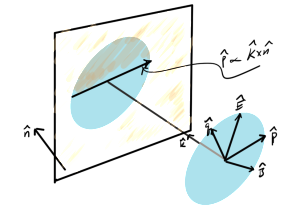
In order to apply the Fresnel equations, the field components have to be resolved into components where either the electric field or the magnetic field is parallel to the plane of reflection. The geometry of this, with the wave vector direction \( \kcap \) and the electric and magnetic field phasors perpendicular to that direction is sketched in fig. 1.

resolvingFieldsIncidentOnObliquePlaneFig1

fig. 1. Field components relative to reflecting plane


If the incident wave is a plane wave, or equivalently a far field spherical wave, it will have the form

\begin{equation}\label{eqn:resolvingFieldsIncidentOnPlane:20}
\BH = \inv{\mu_0} \kcap \cross \BE,
\end{equation}

with the field directions and wave vector directions satisfying

\begin{equation}\label{eqn:resolvingFieldsIncidentOnPlane:60}
\Ecap \cross \Hcap = \kcap
\end{equation}
\begin{equation}\label{eqn:resolvingFieldsIncidentOnPlane:80}
\Ecap \cdot \kcap = 0
\end{equation}
\begin{equation}\label{eqn:resolvingFieldsIncidentOnPlane:100}
\Hcap \cdot \kcap = 0.
\end{equation}

The key to resolving the fields into components parallel to the plane of reflection lies in the observation that the cross product of the plane normal \( \ncap \) and the incident wave vector direction \( \kcap \) lies in that plane. With

\begin{equation}\label{eqn:resolvingFieldsIncidentOnPlane:140}
\pcap = \frac{\kcap \cross \ncap}{\Abs{\kcap \cross \ncap}}
\end{equation}
\begin{equation}\label{eqn:resolvingFieldsIncidentOnPlane:160}
\qcap = \kcap \cross \pcap,
\end{equation}

the field directions can be resolved into components

\begin{equation}\label{eqn:resolvingFieldsIncidentOnPlane:200}
\BE = \lr{ \BE \cdot \pcap } \pcap + \lr{ \BE \cdot \qcap } \qcap = E_\parallel \pcap + E_\perp \qcap
\end{equation}
\begin{equation}\label{eqn:resolvingFieldsIncidentOnPlane:220}
\BH = \lr{ \BH \cdot \pcap } \pcap + \lr{ \BH \cdot \qcap } \qcap = H_\parallel \pcap + H_\perp \qcap.
\end{equation}

This subdivides the fields into two pairs, one with the electric field parallel to the reflection plane

\begin{equation}\label{eqn:resolvingFieldsIncidentOnPlane:240}
\begin{aligned}
\BE_1 &= \lr{ \BE \cdot \pcap } \pcap = E_\parallel \pcap \\
\BH_1 &= \lr{ \BH \cdot \qcap } \qcap = H_\perp \qcap,
\end{aligned}
\end{equation}

and one with the magnetic field parallel to the reflection plane

\begin{equation}\label{eqn:resolvingFieldsIncidentOnPlane:260}
\begin{aligned}
\BH_2 &= \lr{ \BH \cdot \pcap } \pcap = H_\parallel \pcap \\
\BE_2 &= \lr{ \BE \cdot \qcap } \qcap = E_\perp \qcap.
\end{aligned}
\end{equation}

This is most of what we need to proceed with the reflection and transmission analysis. The only task remaining is to determine the reflection angle.

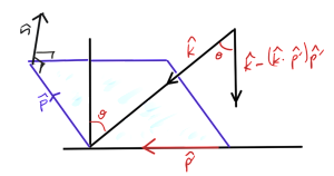
Using a pencil with the tip on the table I was able to convince myself by observation that there is always a normal plane of incidence regardless of any oblique angle that the ray hits the reflecting surface. This was, for some reason, not intuitively obvious to me. Having done that, the geometry must be reduced to what is sketched in fig. 2.

resolvingAngleOfIncidenceFig1

fig. 2. Angle of incidence determination


Once \( \pcap \) has been determined, regardless of it’s orientation in the reflection plane, the component of \( \kcap \) that is normal, directed towards, the plane of reflection is

\begin{equation}\label{eqn:resolvingFieldsIncidentOnPlane:280}
\kcap – \lr{ \kcap \cdot \pcap } \pcap,
\end{equation}

with (squared) length

\begin{equation}\label{eqn:resolvingFieldsIncidentOnPlane:300}
\begin{aligned}
\lr{ \kcap – \lr{ \kcap \cdot \pcap } \pcap }^2
&=
1 + \lr{ \kcap \cdot \pcap }^2 – 2 \lr{ \kcap \cdot \pcap }^2 \\
&=
1 – \lr{ \kcap \cdot \pcap }^2.
\end{aligned}
\end{equation}

The angle of incidence, relative to the normal to the reflection plane, follows from

\begin{equation}\label{eqn:resolvingFieldsIncidentOnPlane:320}
\begin{aligned}
\cos\theta
&= \kcap \cdot \frac{
\kcap – \lr{ \kcap \cdot \pcap } \pcap }{
\sqrt{
1 – \lr{ \kcap \cdot \pcap }^2
}
} \\
&=
\sqrt{
1 – \lr{ \kcap \cdot \pcap }^2
},
\end{aligned}
\end{equation}

Expanding the dot product above gives

\begin{equation}\label{eqn:resolvingFieldsIncidentOnPlane:360}
\begin{aligned}
\kcap \cdot \pcap’
&=
\kcap \cdot \lr{ \pcap \cross \ncap } \\
&=
\frac{1}{\Abs{\kcap \cross \ncap} } \kcap \cdot \lr{ \lr{\kcap \cross \ncap} \cross \ncap },
\end{aligned}
\end{equation}

where

\begin{equation}\label{eqn:resolvingFieldsIncidentOnPlane:380}
\begin{aligned}
\kcap \cdot \lr{ \lr{\kcap \cross \ncap} \cross \ncap }
&=
k_r \epsilon_{r s t} \lr{\kcap \cross \ncap}_s n_t \\
&=
k_r \epsilon_{r s t} \epsilon_{s a b} k_a n_b n_t \\
&=
-k_r \delta_{r t}^{[a b]} k_a n_b n_t \\
&=
-k_r n_t \lr{ k_r n_t – k_t n_r } \\
&=
-1 + \lr{ \kcap \cdot \ncap}^2.
\end{aligned}
\end{equation}

That gives

\begin{equation}\label{eqn:resolvingFieldsIncidentOnPlane:400}
\begin{aligned}
\kcap \cdot \pcap’
&=
\frac{-1 + \lr{ \kcap \cdot \ncap}^2}{\sqrt{1 – \lr{ \kcap \cdot \ncap}^2} } \\
&=
-\sqrt{1 – \lr{ \kcap \cdot \ncap}^2},
\end{aligned}
\end{equation}

or

\begin{equation}\label{eqn:resolvingFieldsIncidentOnPlane:420}
\begin{aligned}
\cos\theta
&= \sqrt{ 1 – \lr{-\sqrt{1 – \lr{ \kcap \cdot \ncap}^2}}^2 } \\
&= \sqrt{ \lr{ \kcap \cdot \ncap}^2 } \\
&= \kcap \cdot \ncap.
\end{aligned}
\end{equation}

This surprisingly simple result makes so much sense, it is an awful admission of stupidity that I went through all the vector algebra to get it instead of just writing it down directly.

The end result is the reflection angle is given by

\begin{equation}\label{eqn:resolvingFieldsIncidentOnPlane:340}
\boxed{
\theta = \cos^{-1} \kcap \cdot \ncap,
}
\end{equation}

where the reflection plane normal should off the back surface to get the sign right. The only detail left is the vector direction of the reflected ray (as well as the direction for the transmitted ray if that is of interest). The reflected ray direction flips the sign of the normal component of the ray

\begin{equation}\label{eqn:resolvingFieldsIncidentOnPlane:440}
\begin{aligned}
\kcap’
&= -\lr{\kcap \cdot \ncap} \ncap + \lr{ \kcap \wedge \ncap} \ncap \\
&= -\lr{\kcap \cdot \ncap} \ncap + \kcap – \lr{ \ncap \kcap} \cdot \ncap \\
&= \kcap -2 \lr{\kcap \cdot \ncap} \ncap.
\end{aligned}
\end{equation}

Here the sign of the normal doesn’t matter since it only occurs quadratically.

This now supplies everything needed for the application of the Fresnel equations to determine the reflected ray characteristics of an arbitrarily polarized incident field.

Duality transformation

March 2, 2015 ece1229 , , , , , ,

[Click here for a PDF of this post with nicer formatting]

In a discussion of Dirac’s monopoles, [1] introduces a duality transformation, forming electric and magnetic fields by forming a rotation that combines a different pair of electric and magnetic fields. In SI units that transformation becomes

\begin{equation}\label{eqn:dualityTransformation:40}
\begin{bmatrix}
\boldsymbol{\mathcal{E}} \\
\eta \boldsymbol{\mathcal{H}}
\end{bmatrix}
=
\begin{bmatrix}
\cos\theta & \sin\theta \\
-\sin\theta & \cos\theta
\end{bmatrix}
\begin{bmatrix}
\boldsymbol{\mathcal{E}}’ \\
\eta \boldsymbol{\mathcal{H}}’
\end{bmatrix}
\end{equation}
\begin{equation}\label{eqn:dualityTransformation:60}
\begin{bmatrix}
\boldsymbol{\mathcal{D}} \\
\boldsymbol{\mathcal{B}}/\eta
\end{bmatrix}
=
\begin{bmatrix}
\cos\theta & \sin\theta \\
-\sin\theta & \cos\theta
\end{bmatrix}
\begin{bmatrix}
\boldsymbol{\mathcal{D}}’ \\
\boldsymbol{\mathcal{B}}’/\eta
\end{bmatrix},
\end{equation}

where \( \eta = \sqrt{\mu_0/\epsilon_0} \). It is left as an exercise to the reader to show that application of these to Maxwell’s equations

\begin{equation}\label{eqn:dualityTransformation:100}
\spacegrad \cdot \boldsymbol{\mathcal{E}} = \rho_{\textrm{e}}/\epsilon_0
\end{equation}
\begin{equation}\label{eqn:dualityTransformation:120}
\spacegrad \cdot \boldsymbol{\mathcal{H}} = \rho_{\textrm{m}}/\mu_0
\end{equation}
\begin{equation}\label{eqn:dualityTransformation:140}
-\spacegrad \cross \boldsymbol{\mathcal{E}} – \partial_t \boldsymbol{\mathcal{B}} = \boldsymbol{\mathcal{J}}_{\textrm{m}}
\end{equation}
\begin{equation}\label{eqn:dualityTransformation:160}
\spacegrad \cross \boldsymbol{\mathcal{H}} – \partial_t \boldsymbol{\mathcal{D}} = \boldsymbol{\mathcal{J}}_{\textrm{e}},
\end{equation}

determine a similar relation between the sources. That transformation of Maxwell’s equation is

\begin{equation}\label{eqn:dualityTransformation:200}
\spacegrad \cdot \lr{ \cos\theta \boldsymbol{\mathcal{E}}’ + \sin\theta \eta \boldsymbol{\mathcal{H}}’ } = \rho_{\textrm{e}}/\epsilon_0
\end{equation}
\begin{equation}\label{eqn:dualityTransformation:220}
\spacegrad \cdot \lr{ -\sin\theta \boldsymbol{\mathcal{E}}’/\eta + \cos\theta \boldsymbol{\mathcal{H}}’ } = \rho_{\textrm{m}}/\mu_0
\end{equation}
\begin{equation}\label{eqn:dualityTransformation:240}
-\spacegrad \cross \lr{ \cos\theta \boldsymbol{\mathcal{E}}’ + \sin\theta \eta \boldsymbol{\mathcal{H}}’ } – \partial_t \lr{ – \sin\theta \eta \boldsymbol{\mathcal{D}}’ + \cos\theta \boldsymbol{\mathcal{B}}’ } = \boldsymbol{\mathcal{J}}_{\textrm{m}}
\end{equation}
\begin{equation}\label{eqn:dualityTransformation:260}
\spacegrad \cross \lr{ -\sin\theta \boldsymbol{\mathcal{E}}’/\eta + \cos\theta \boldsymbol{\mathcal{H}}’ } – \partial_t \lr{ \cos\theta \boldsymbol{\mathcal{D}}’ + \sin\theta \boldsymbol{\mathcal{B}}’/\eta } = \boldsymbol{\mathcal{J}}_{\textrm{e}}.
\end{equation}

A bit of rearranging gives

\begin{equation}\label{eqn:dualityTransformation:400}
\begin{bmatrix}
\eta \rho_{\textrm{e}} \\
\rho_{\textrm{m}}
\end{bmatrix}
=
\begin{bmatrix}
\cos\theta & \sin\theta \\
-\sin\theta & \cos\theta
\end{bmatrix}
\begin{bmatrix}
\eta \rho_{\textrm{e}}’ \\
\rho_{\textrm{m}}’
\end{bmatrix}
\end{equation}
\begin{equation}\label{eqn:dualityTransformation:420}
\begin{bmatrix}
\eta \boldsymbol{\mathcal{J}}_{\textrm{e}} \\
\boldsymbol{\mathcal{J}}_{\textrm{m}} \\
\end{bmatrix}
=
\begin{bmatrix}
\cos\theta & \sin\theta \\
-\sin\theta & \cos\theta
\end{bmatrix}
\begin{bmatrix}
\eta \boldsymbol{\mathcal{J}}_{\textrm{e}}’ \\
\boldsymbol{\mathcal{J}}_{\textrm{m}}’ \\
\end{bmatrix}.
\end{equation}

For example, with \( \rho_{\textrm{m}} = \boldsymbol{\mathcal{J}}_{\textrm{m}} = 0 \), and \( \theta = \pi/2 \), the transformation of sources is

\begin{equation}\label{eqn:dualityTransformation:440}
\begin{aligned}
\rho_{\textrm{e}}’ &= 0 \\
\boldsymbol{\mathcal{J}}_{\textrm{e}}’ &= 0 \\
\rho_{\textrm{m}}’ &= \eta \rho_{\textrm{e}} \\
\boldsymbol{\mathcal{J}}_{\textrm{m}}’ &= \eta \boldsymbol{\mathcal{J}}_{\textrm{e}},
\end{aligned}
\end{equation}

and Maxwell’s equations then have only magnetic sources

\begin{equation}\label{eqn:dualityTransformation:480}
\spacegrad \cdot \boldsymbol{\mathcal{E}}’ = 0
\end{equation}
\begin{equation}\label{eqn:dualityTransformation:500}
\spacegrad \cdot \boldsymbol{\mathcal{H}}’ = \rho_{\textrm{m}}’/\mu_0
\end{equation}
\begin{equation}\label{eqn:dualityTransformation:520}
-\spacegrad \cross \boldsymbol{\mathcal{E}}’ – \partial_t \boldsymbol{\mathcal{B}}’ = \boldsymbol{\mathcal{J}}_{\textrm{m}}’
\end{equation}
\begin{equation}\label{eqn:dualityTransformation:540}
\spacegrad \cross \boldsymbol{\mathcal{H}}’ – \partial_t \boldsymbol{\mathcal{D}}’ = 0.
\end{equation}

Of this relation Jackson points out that “The invariance of the equations of electrodynamics under duality transformations shows that it is a matter of convention to speak of a particle possessing an electric charge, but not magnetic charge.” This is an interesting comment, and worth some additional thought.

References

[1] JD Jackson. Classical Electrodynamics. John Wiley and Sons, 2nd edition, 1975.

Duality transformation of the far field fields.

February 27, 2015 ece1229 , , , ,

We’ve seen that the far field electric and magnetic fields associated with a magnetic vector potential were

\begin{equation}\label{eqn:dualFarField:40}
\BE = -j \omega \textrm{Proj}_\T \BA,
\end{equation}
\begin{equation}\label{eqn:dualFarField:60}
\BH = \inv{\eta} \kcap \cross \BE.
\end{equation}

It’s worth a quick note that the duality transformation for this, referring to [1] tab. 3.2, is

\begin{equation}\label{eqn:dualFarField:100}
\BH = -j \omega \textrm{Proj}_\T \BF
\end{equation}
\begin{equation}\label{eqn:dualFarField:120}
\BE = -\eta \kcap \cross \BH.
\end{equation}

What does \( \BH \) look like in terms of \( \BA \), and \( \BE \) look like in terms of \( \BH \)?

The first is

\begin{equation}\label{eqn:dualFarField:140}
\BH
= -\frac{j \omega}{\eta} \kcap \cross \lr{ \BA – \lr{\BA \cdot \kcap} \kcap },
\end{equation}

in which the \( \kcap \) crossed terms are killed, leaving

\begin{equation}\label{eqn:dualFarField:160}
\BH
= -\frac{j \omega}{\eta} \kcap \cross \BA.
\end{equation}

The electric field follows again using a duality transformation, so in terms of the electric vector potential, is

\begin{equation}\label{eqn:dualFarField:180}
\BE = j \omega \eta \kcap \cross \BF.
\end{equation}

These show explicitly that neither the electric or magnetic far field have any radial component, matching with intuition for transverse propagation of the fields.

References

[1] Constantine A Balanis. Antenna theory: analysis and design. John Wiley & Sons, 3rd edition, 2005.