[Click here for a PDF of this post with nicer formatting]
Motivation
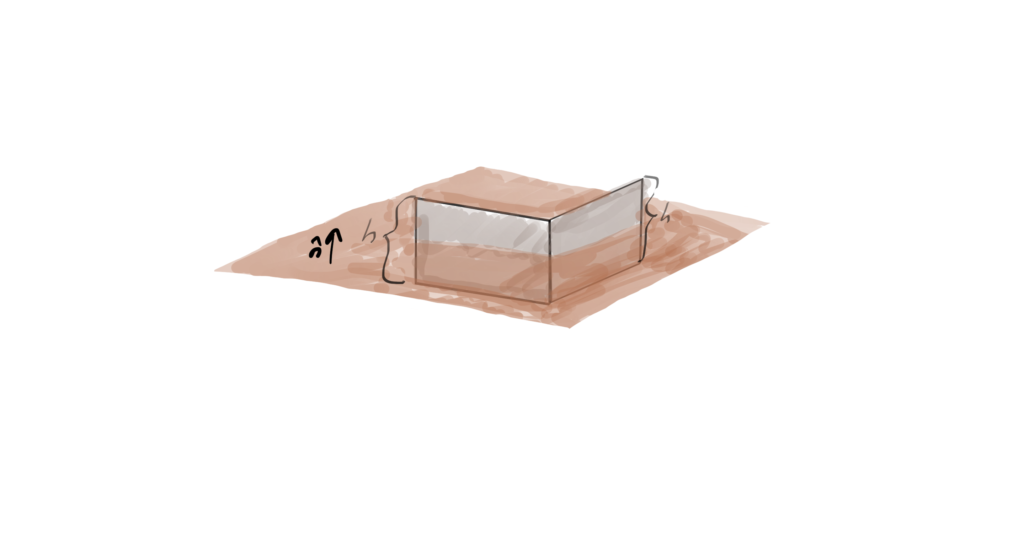
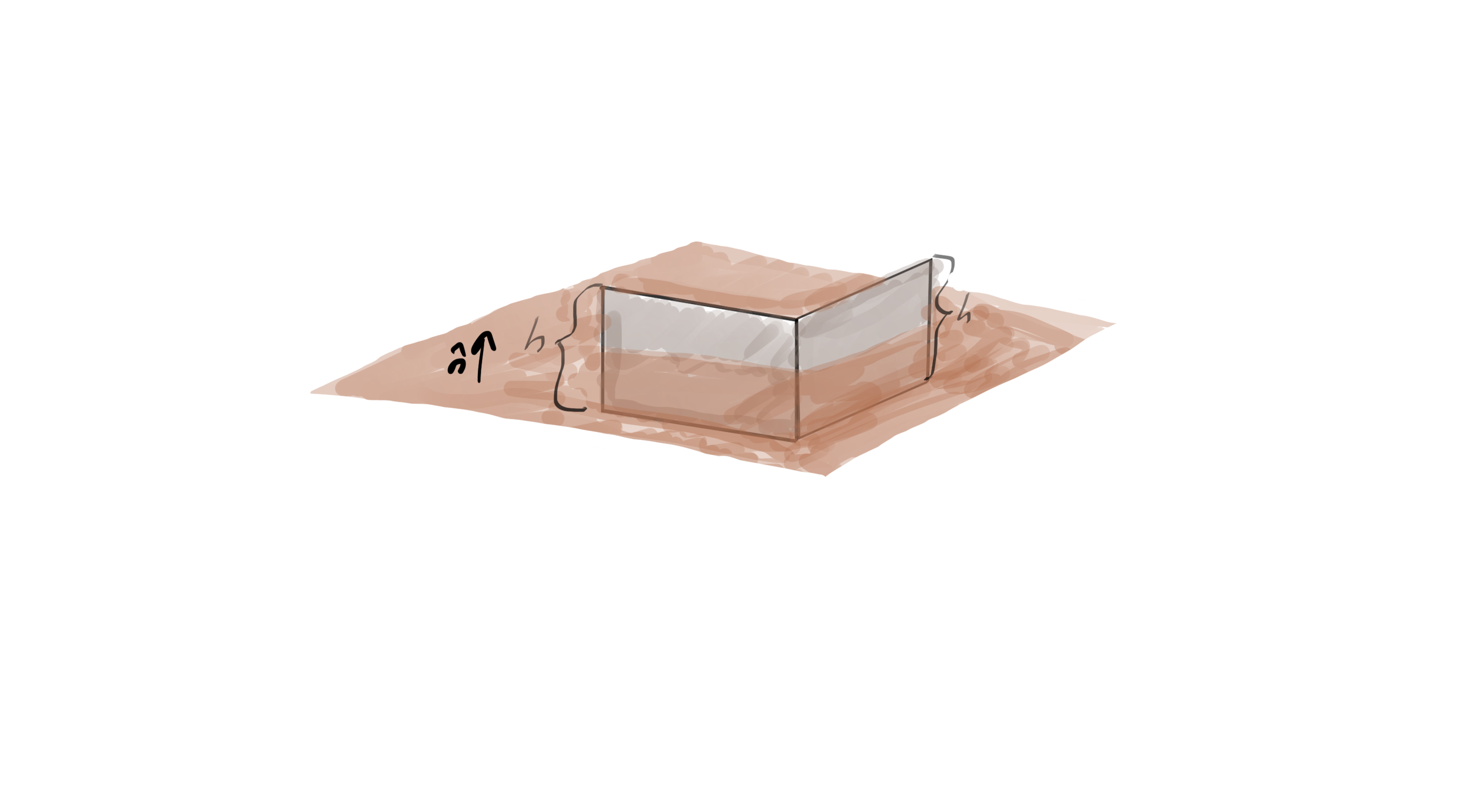
fig 1. Two surfaces normal to the interface.
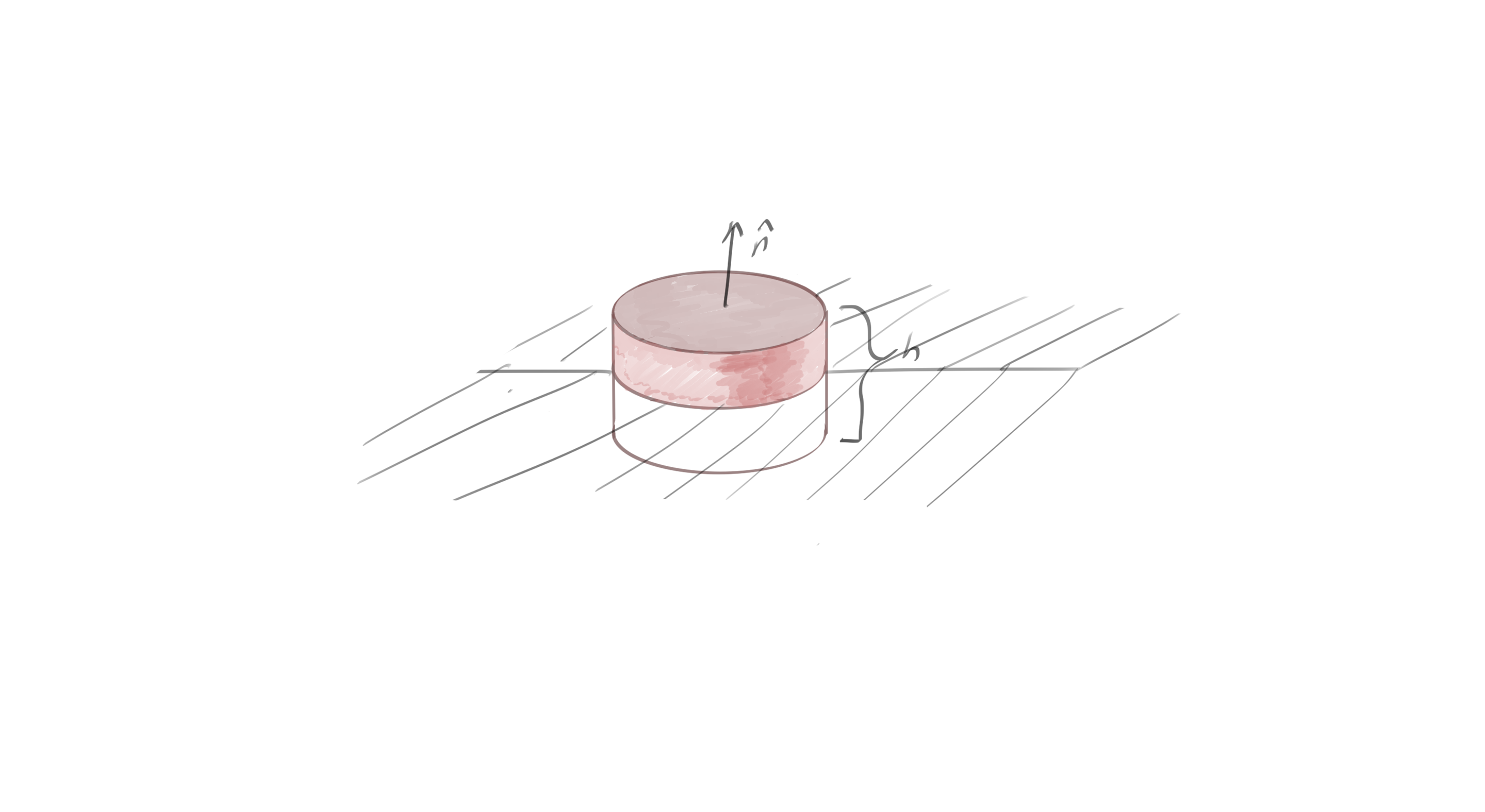
Most electrodynamics textbooks either start with or contain a treatment of boundary value conditions. These typically involve evaluating Maxwell’s equations over areas or volumes of decreasing height, such as those illustrated in fig. 1, and fig. 2. These represent surfaces and volumes where the height is allowed to decrease to infinitesimal levels, and are traditionally used to find the boundary value constraints of the normal and tangential components of the electric and magnetic fields.

fig 2. A pillbox volume encompassing the interface.
More advanced topics, such as evaluation of the Fresnel reflection and transmission equations, also rely on similar consideration of boundary value constraints. I’ve wondered for a long time how the Fresnel equations could be attacked by looking at the boundary conditions for the combined field \( F = \BE + I c \BB \), instead of the considering them separately.
A unified approach.
The Geometric Algebra (and relativistic tensor) formulations of Maxwell’s equations put the electric and magnetic fields on equal footings. It is in fact possible to specify the boundary value constraints on the fields without first separating Maxwell’s equations into their traditional forms. The starting point in Geometric Algebra is Maxwell’s equation, premultiplied by a stationary observer’s timelike basis vector
\begin{equation}\label{eqn:maxwellBoundaryConditions:20}
\gamma_0 \grad F = \inv{\epsilon_0 c} \gamma_0 J,
\end{equation}
or
\begin{equation}\label{eqn:maxwellBoundaryConditions:40}
\lr{ \partial_0 + \spacegrad} F = \frac{\rho}{\epsilon_0} – \frac{\BJ}{\epsilon_0}.
\end{equation}
The electrodynamic field \(F = \BE + I c \BB\) is a multivector in this spatial domain (whereas it is a bivector in the spacetime algebra domain), and has vector and bivector components. The product of the spatial gradient and the field can still be split into dot and curl components \(\spacegrad M = \spacegrad \cdot M + \spacegrad \wedge M \). If \(M = \sum M_i \), where \(M_i\) is an grade \(i\) blade, then we give this the Hestenes’ [1] definitions
\begin{equation}\label{eqn:maxwellBoundaryConditions:60}
\begin{aligned}
\spacegrad \cdot M &= \sum_i \gpgrade{\spacegrad M_i}{i-1} \\
\spacegrad \wedge M &= \sum_i \gpgrade{\spacegrad M_i}{i+1}.
\end{aligned}
\end{equation}
With that said, Maxwell’s equation can be rearranged into a pair of multivector equations
\begin{equation}\label{eqn:maxwellBoundaryConditions:80}
\begin{aligned}
\spacegrad \cdot F &= \gpgrade{-\partial_0 F + \frac{\rho}{\epsilon_0} – \frac{\BJ}{\epsilon_0 c}}{0,1} \\
\spacegrad \wedge F &= \gpgrade{-\partial_0 F + \frac{\rho}{\epsilon_0} – \frac{\BJ}{\epsilon_0 c}}{2,3},
\end{aligned}
\end{equation}
The latter equation can be integrated with Stokes theorem, but we need to apply a duality transformation to the latter in order to apply Stokes to it
\begin{equation}\label{eqn:maxwellBoundaryConditions:120}
\begin{aligned}
\spacegrad \cdot F
&=
-I^2 \spacegrad \cdot F \\
&=
-I^2 \gpgrade{\spacegrad F}{0,1} \\
&=
-I \gpgrade{I \spacegrad F}{2,3} \\
&=
-I \spacegrad \wedge (IF),
\end{aligned}
\end{equation}
so
\begin{equation}\label{eqn:maxwellBoundaryConditions:100}
\begin{aligned}
\spacegrad \wedge (I F) &= I \lr{ -\inv{c} \partial_t \BE + \frac{\rho}{\epsilon_0} – \frac{\BJ}{\epsilon_0 c} } \\
\spacegrad \wedge F &= -I \partial_t \BB.
\end{aligned}
\end{equation}
Integrating each of these over the pillbox volume gives
\begin{equation}\label{eqn:maxwellBoundaryConditions:140}
\begin{aligned}
\oint_{\partial V} d^2 \Bx \cdot (I F)
&=
\int_{V} d^3 \Bx \cdot \lr{ I \lr{ -\inv{c} \partial_t \BE + \frac{\rho}{\epsilon_0} – \frac{\BJ}{\epsilon_0 c} } } \\
\oint_{\partial V} d^2 \Bx \cdot F
&=
– \partial_t \int_{V} d^3 \Bx \cdot \lr{ I \BB }.
\end{aligned}
\end{equation}
In the absence of charges and currents on the surface, and if the height of the volume is reduced to zero, the volume integrals vanish, and only the upper surfaces of the pillbox contribute to the surface integrals.
\begin{equation}\label{eqn:maxwellBoundaryConditions:200}
\begin{aligned}
\oint_{\partial V} d^2 \Bx \cdot (I F) &= 0 \\
\oint_{\partial V} d^2 \Bx \cdot F &= 0.
\end{aligned}
\end{equation}
With a multivector \(F\) in the mix, the geometric meaning of these integrals is not terribly clear. They do describe the boundary conditions, but to see exactly what those are, we can now resort to the split of \(F\) into its electric and magnetic fields. Let’s look at the non-dual integral to start with
\begin{equation}\label{eqn:maxwellBoundaryConditions:160}
\begin{aligned}
\oint_{\partial V} d^2 \Bx \cdot F
&=
\oint_{\partial V} d^2 \Bx \cdot \lr{ \BE + I c \BB } \\
&=
\oint_{\partial V} d^2 \Bx \cdot \BE + I c d^2 \Bx \wedge \BB \\
&=
0.
\end{aligned}
\end{equation}
No component of \(\BE\) that is normal to the surface contributes to \(d^2 \Bx \cdot \BE \), whereas only components of \(\BB\) that are normal contribute to \(d^2 \Bx \wedge \BB \). That means that we must have tangential components of \(\BE\) and the normal components of \(\BB\) matching on the surfaces
\begin{equation}\label{eqn:maxwellBoundaryConditions:180}
\begin{aligned}
\lr{\BE_2 \wedge \ncap} \ncap – \lr{\BE_1 \wedge (-\ncap)} (-\ncap) &= 0 \\
\lr{\BB_2 \cdot \ncap} \ncap – \lr{\BB_1 \cdot (-\ncap)} (-\ncap) &= 0 .
\end{aligned}
\end{equation}
Similarly, for the dot product of the dual field, this is
\begin{equation}\label{eqn:maxwellBoundaryConditions:220}
\begin{aligned}
\oint_{\partial V} d^2 \Bx \cdot (I F)
&=
\oint_{\partial V} d^2 \Bx \cdot (I \BE – c \BB) \\
&=
\oint_{\partial V} I d^2 \Bx \wedge \BE – c d^2 \Bx \cdot \BB.
\end{aligned}
\end{equation}
For this integral, only the normal components of \(\BE\) contribute, and only the tangential components of \(\BB\) contribute. This means that
\begin{equation}\label{eqn:maxwellBoundaryConditions:240}
\begin{aligned}
\lr{\BE_2 \cdot \ncap} \ncap – \lr{\BE_1 \cdot (-\ncap)} (-\ncap) &= 0 \\
\lr{\BB_2 \wedge \ncap} \ncap – \lr{\BB_1 \wedge (-\ncap)} (-\ncap) &= 0.
\end{aligned}
\end{equation}
This is why we end up with a seemingly strange mix of tangential and normal components of the electric and magnetic fields. These constraints can be summarized as
\begin{equation}\label{eqn:maxwellBoundaryConditions:260}
\begin{aligned}
( \BE_2 – \BE_1 ) \cdot \ncap &= 0 \\
( \BE_2 – \BE_1 ) \wedge \ncap &= 0 \\
( \BB_2 – \BB_1 ) \cdot \ncap &= 0 \\
( \BB_2 – \BB_1 ) \wedge \ncap &= 0
\end{aligned}
\end{equation}
These relationships are usually expressed in terms of all of \(\BE, \BD, \BB\) and \(\BH \). Because I’d started with Maxwell’s equations for free space, I don’t have the \( \epsilon \) and \( \mu \) factors that produce those more general relationships. Those more general boundary value relationships are usually the starting point for the Fresnel interface analysis. It is also possible to further generalize these relationships to include charges and currents on the surface.
References
[1] D. Hestenes. New Foundations for Classical Mechanics. Kluwer Academic Publishers, 1999.