Month: November 2014

ECE1254H Modeling of Multiphysics Systems. Lecture 15: Nonlinear differential equations. Taught by Prof. Piero Triverio

November 12, 2014 ece1254 , , , , , , , ,

[Click here for a PDF of this post with nicer formatting]

Disclaimer

Peeter’s lecture notes from class. These may be incoherent and rough.

Nonlinear differential equations

Assume that the relationships between the zeroth and first order derivatives has the form

\begin{equation}\label{eqn:multiphysicsL15:20}
F\lr{ x(t), \dot{x}(t) } = 0
\end{equation}
\begin{equation}\label{eqn:multiphysicsL15:40}
x(0) = x_0
\end{equation}

The backward Euler method where the derivative approximation is

\begin{equation}\label{eqn:multiphysicsL15:60}
\dot{x}(t_n) \approx \frac{x_n – x_{n-1}}{\Delta t},
\end{equation}

can be used to solve this numerically, reducing the problem to

\begin{equation}\label{eqn:multiphysicsL15:80}
F\lr{ x_n, \frac{x_n – x_{n-1}}{\Delta t} } = 0.
\end{equation}

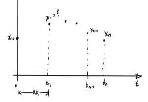
This can be solved with Newton’s method. How do we find the initial guess for Newton’s? Consider a possible system in fig. 1.

lecture15Fig1

fig. 1. Possible solution points


One strategy for starting each iteration of Newton’s method is to base the initial guess for \( x_1 \) on the value \( x_0 \), and do so iteratively for each subsequent point. One can imagine that this may work up to some sample point \( x_n \), but then break down (i.e. Newton’s diverges when the previous value \( x_{n-1} \) is used to attempt to solve for \( x_n \)). At that point other possible strategies may work. One such strategy is to use an approximation of the derivative from the previous steps to attempt to get a better estimate of the next value. Another possibility is to reduce the time step, so the difference between successive points is reduced.

Analysis, accuracy and stability (\(\Delta t \rightarrow 0\))

Consider a differential equation

\begin{equation}\label{eqn:multiphysicsL15:100}
\dot{x}(t) = f(x(t), t)
\end{equation}
\begin{equation}\label{eqn:multiphysicsL15:120}
x(t_0) = x_0
\end{equation}

A few methods of solution have been considered

  • (FE) \( x_{n+1} – x_n = \Delta t f(x_n, t_n) \)
  • (BE) \( x_{n+1} – x_n = \Delta t f(x_{n+1}, t_{n+1}) \)
  • (TR) \( x_{n+1} – x_n = \frac{\Delta t}{2} f(x_{n+1}, t_{n+1}) + \frac{\Delta t}{2} f(x_{n}, t_{n}) \)

A common pattern can be observed, the generalization of which are called
\textit{linear multistep methods}
(LMS), which have the form

\begin{equation}\label{eqn:multiphysicsL15:140}
\sum_{j=-1}^{k-1} \alpha_j x_{n-j} = \Delta t \sum_{j=-1}^{k-1} \beta_j f( x_{n-j}, t_{n-j} )
\end{equation}

The FE (explicit), BE (implicit), and TR methods are now special cases with

  • (FE) \( \alpha_{-1} = 1, \alpha_0 = -1, \beta_{-1} = 0, \beta_0 = 1 \)
  • (BE) \( \alpha_{-1} = 1, \alpha_0 = -1, \beta_{-1} = 1, \beta_0 = 0 \)
  • (TR) \( \alpha_{-1} = 1, \alpha_0 = -1, \beta_{-1} = 1/2, \beta_0 = 1/2 \)

Here \( k \) is the number of timesteps used. The method is explicit if \( \beta_{-1} = 0 \).

Definition: Convergence

With

  • \(x(t)\) : exact solution
  • \(x_n\) : computed solution
  • \(e_n\) : where \( e_n = x_n – x(t_n) \), is the global error

The LMS method is convergent if

\begin{equation*}%\label{eqn:multiphysicsL15:180}
\max_{n, \Delta t \rightarrow 0} \Abs{ x_n – t(t_n) } \rightarrow 0 %\xrightarrow[t \rightarrow 0 ]{} 0
\end{equation*}

Convergence: zero-stability and consistency (small local errors made at each iteration),

where zero-stability is “small sensitivity to changes in initial condition”.

Definition: Consistency

A local error \( R_{n+1} \) can be defined as

\begin{equation*}%\label{eqn:multiphysicsL15:220}
R_{n+1} = \sum_{j = -1}^{k-1} \alpha_j x(t_{n-j}) – \Delta t \sum_{j=-1}^{k-1} \beta_j f(x(t_{n-j}), t_{n-j}).
\end{equation*}

The method is consistent if

\begin{equation*}%\label{eqn:multiphysicsL15:240}
\lim_{\Delta t} \lr{
\max_n \Abs{ \inv{\Delta t} R_{n+1} } = 0
}
\end{equation*}

or \( R_{n+1} \sim O({\Delta t}^2) \)
Remembrance day, a celebration and glorification of war

November 11, 2014 Incoherent ramblings

Today I received the following Remembrance day message at work:

“Every year on November 11th, Canadians pause for a moment of silence in remembrance of the men and women who have served our country during times of war, conflict and peace. More than 1,500,000 Canadians have served our country in this way and over 100,000 have paid the ultimate sacrifice.

They gave their lives and their futures for the freedoms we enjoy today.

At 11:00 a.m. today, please join me in observing one full minute of silence.

This illustrates precisely the sort of propaganda that is buried in this yearly celebration of war. Many people will object to my labeling of Remembrance day as a celebration of war, but I think that is an apt label.

We should remember the collective insanity that drove so many to send themselves off to be killed or kill. We should remember those who profited from the wars, and those who funded both sided. Let’s remember the Carnegies who concluded that there’s no better industry than war for profits and pleaded to Wilson to not end world war I too quickly. We should remember the massive propaganda campaigns to attempt to coerce people into fighting these wars. We should remember the disgusting lies that have been used again and again to justify wars that are later proven false. We should remember the US companies like Ford and IBM (my current employer!) that provided financial and resource backing to Hitler, without which his final atrocities would not have been possible. We should remember how every war has been an excuse for raising taxes to new peaks, raising nationalistic debt servitude at every turn (*). We should remember that civilians are the people most hurt by wars, and not focus our attentions on those soldiers that held the guns or were shot by them.

There are many things to remember, and if we are deluded into focusing our attention on the “sacrifices of soldiers”, who are pawns in the grand scheme of things, then we loose.

It is interesting to see just how transparent the Remembrance day propaganda can be. It is not just the glorification of the soldiers who were killed and did their killing. We are asked specifically to also glorify the people that “serve” Canada in it’s day to day waging of what amounts to US imperialistic warfare in times of peace.

Ron Paul’s recent commentary on Canada’s current war mongering nature was very apt.  We should remember that the aggressions that happen in our names have consequences.

If it were not for acceptance of the sorts of patriotic drivel that we see on Remembrance day, and patriotism conditioning events like the daily standing for the national anthem, perhaps a few less people would be so willing to fight wars for or against governments that are not worth obeying.

We give governments power by sheepish compliance. This service is to an entity that is a figment of our collective agreement.

Today I’ll actually just remember my dad. He is the only person I knew that saw through the social conditioning of Remembrance day and so aptly identified it as a propaganda event.


Footnotes:

(*) I’m not sure how definitive the debtclock link above is, nor it’s sources.  Here’s a newer Canadian debt-clock.  That site is currently also vague about it’s sources, citing “Canadian Government Data” without specifying them, nor linking to them.

ECE1254H Modeling of Multiphysics Systems. Lecture 14: Backward Euler method and trapezoidal methods. Taught by Prof. Piero Triverio

November 10, 2014 ece1254 , , ,

[Click here for a PDF of this post with nicer formatting]

Disclaimer

Peeter’s lecture notes from class. These may be incoherent and rough.

Backward Euler method

Discretized time dependent partial differential equations were seen to have the form

\begin{equation}\label{eqn:multiphysicsL14:20}
G \Bx(t) + C \dot{\Bx}(t) = B \Bu(t),
\end{equation}

where \( G, C, B \) are matrices, and \( \Bu(t) \) is a vector of sources.

The backward Euler method augments \ref{eqn:multiphysicsL14:20} with an initial condition. For a one dimensional system such an initial condition could a zero time specification

\begin{equation}\label{eqn:multiphysicsL14:40}
G x(t) + C \dot{x}(t) = B u(t),
\end{equation}
\begin{equation}\label{eqn:multiphysicsL14:60}
x(0) = x_0
\end{equation}

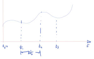
Discretizing time as in fig. 1.

lecture14Fig1

fig. 1. Discretized time

The discrete derivative, using a backward difference, is

\begin{equation}\label{eqn:multiphysicsL14:80}
\dot{x}(t = t_n) \approx \frac{ x_n – x_{n-1} }{\Delta t}
\end{equation}

Evaluating \ref{eqn:multiphysicsL14:40} at \( t = t_n \) is

\begin{equation}\label{eqn:multiphysicsL14:100}
G x_n + C \dot{x}(t = t_n) = B u(t_n),
\end{equation}

or approximately

\begin{equation}\label{eqn:multiphysicsL14:120}
G x_n + C \frac{x_n – x_{n-1}}{\Delta t} = B u(t_n).
\end{equation}

Rearranging

\begin{equation}\label{eqn:multiphysicsL14:140}
\lr{ G + \frac{C}{\Delta t} } x_n = \frac{C}{\Delta t} x_{n-1}
+
B u(t_n).
\end{equation}

Assuming that matrices \( G, C \) are constant, and \( \Delta t \) is fixed, a matrix inversion can be avoided, and a single LU decomposition can be used. For \( N \) sampling points (not counting \( t_0 = 0 \)), \( N \) sets of backward and forward substitutions will be required to compute \( x_1 \) from \( x_0 \), and so forth.

Backwards Euler is an implicit method.

Recall that the forward Euler method gave

\begin{equation}\label{eqn:multiphysicsL14:160}
x_{n+1} =
x_n \lr{ I – C^{-1} \Delta t G }
+ C^{-1} \Delta t B u(t_n)
\end{equation}

This required

  • \( C \) must be invertible.
  • \( C \) must be cheap to invert, perhaps \( C = I \), so that
    \begin{equation}\label{eqn:multiphysicsL14:180}
    x_{n+1} =
    \lr{ I – \Delta t G } x_n
    + \Delta t B u(t_n)
    \end{equation}
  • This is an explicit method
  • This can be cheap but unstable.

Trapezoidal rule (TR)

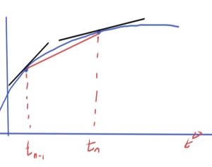
The derivative can be approximated using an average of the pair of derivatives as illustrated in fig. 2.

lecture14Fig2

fig. 2. Trapezoidal derivative approximation

\begin{equation}\label{eqn:multiphysicsL14:200}
\frac{x_n – x_{n-1}}{\Delta t} \approx \frac{
\dot{x}(t_{n-1})
+
\dot{x}(t_{n})
}
{2}.
\end{equation}

Application to \ref{eqn:multiphysicsL14:40} for \( t_{n-1}, t_n \) respectively gives

\begin{equation}\label{eqn:multiphysicsL14:220}
\begin{aligned}
G x_{n-1} + C \dot{x}(t_{n-1}) &= B u(t_{n-1}) \\
G x_{n} + C \dot{x}(t_{n}) &= B u(t_{n}) \\
\end{aligned}
\end{equation}

Averaging these

\begin{equation}\label{eqn:multiphysicsL14:240}
G \frac{ x_{n-1} + x_n }{2} + C
\frac{
\dot{x}(t_{n-1})
+\dot{x}(t_{n})
}{2}
= B
\frac{u(t_{n-1})
+
u(t_{n}) }{2},
\end{equation}

and inserting the trapezoidal approximation

\begin{equation}\label{eqn:multiphysicsL14:280}
G \frac{ x_{n-1} + x_n }{2}
+
C
\frac{
x_{n} –
x_{n-1}
}{\Delta t}
= B
\frac{u(t_{n-1})
+
u(t_{n}) }{2},
\end{equation}

and a final rearrangement yields

\begin{equation}\label{eqn:multiphysicsL14:260}
\boxed{
\lr{ G + \frac{2}{\Delta t} C } x_n
=

\lr{ G – \frac{2}{\Delta t} C } x_{n_1}
+ B
\lr{u(t_{n-1})
+
u(t_{n}) }.
}
\end{equation}

This is

  • also an implicit method.
  • requires LU of \( G – 2 C /\Delta t \).
  • more accurate than BE, for the same computational cost.

In all of these methods, accumulation of error is something to be very careful of, and in some cases such error accumulation can even be exponential.

This is effectively a way to introduce central differences. On the slides this is seen to be more effective at avoiding either artificial damping and error accumulation that can be seen in backwards and forwards Euler method respectively.

Make a difference, sponsor a warlord — CIA advertisement

November 10, 2014 Just for fun , , , , ,

The Toike Oike, UofT’s engineering newspaper, has reached majestic heights of spoof advertisement in the November issue, with the following advert placed by the CIA

make a difference sponser a warlord, CIA advertisment

The sad thing is that there is so much truth embedded in this bit of parody.

I congratulate the author for most excellent work. Very nice work! Oh, and finding the smiling guy in fatigues with his gun toting buddies in the background was a real nice compositional touch.

Simple Norton equivalents

November 10, 2014 ece1254 , ,

[Click here for a PDF of this post with nicer formatting]

The problem set contained a circuit with constant voltage source that made the associated Nodal matrix non-symmetric. There was a hint that this source \( V_s \) and its internal resistance \( R_s \) can likely be replaced by a constant current source.

Here two voltage source configurations will be compared to a current source configuration, with the assumption that equivalent circuit configurations can be found.

First voltage source configuration

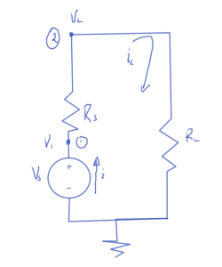
First consider the source and internal series resistance configuration sketched in fig. 1, with a purely resistive load.

nortonEquivalentFig1

fig. 1. First voltage source configuration

The nodal equations for this system are

  1. \( -i_L + (V_1 – V_L) Z_s = 0 \)
  2. \( V_L Z_L + (V_L – V_1) Z_s = 0 \)
  3. \( V_1 = V_s \)

In matrix form these are

\begin{equation}\label{eqn:simpleNortonEquivalents:20}
\begin{bmatrix}
Z_s & -Z_s & -1 \\
-Z_s & Z_s + Z_L & 0 \\
1 & 0 & 0
\end{bmatrix}
\begin{bmatrix}
V_1 \\
V_L \\
i_L
\end{bmatrix}
=
\begin{bmatrix}
0 \\
0 \\
V_s
\end{bmatrix}
\end{equation}

This has solution

\begin{equation}\label{eqn:simpleNortonEquivalents:40}
V_L = V_s \frac{ R_L }{R_L + R_s}
\end{equation}
\begin{equation}\label{eqn:simpleNortonEquivalents:100}
i_L = \frac{V_s}{R_L + R_s}
\end{equation}
\begin{equation}\label{eqn:simpleNortonEquivalents:120}
V_1 = V_s.
\end{equation}

Second voltage source configuration

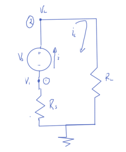
Now consider the same voltage source, but with the series resistance location flipped as sketched in fig. 2.

nortonEquivalentFig2

fig. 2. Second voltage source configuration

The nodal equations are

  1. \( V_1 Z_s + i_L = 0 \)
  2. \( -i_L + V_L Z_L = 0 \)
  3. \( V_L – V_1 = V_s \)

These have matrix form

\begin{equation}\label{eqn:simpleNortonEquivalents:60}
\begin{bmatrix}
Z_s & 0 & 1 \\
0 & Z_L & -1 \\
-1 & 1 & 0
\end{bmatrix}
\begin{bmatrix}
V_1 \\
V_L \\
i_L
\end{bmatrix}
=
\begin{bmatrix}
0 \\
0 \\
V_s
\end{bmatrix}
\end{equation}

This configuration has solution

\begin{equation}\label{eqn:simpleNortonEquivalents:50}
V_L = V_s \frac{ R_L }{R_L + R_s}
\end{equation}
\begin{equation}\label{eqn:simpleNortonEquivalents:180}
i_L = \frac{V_s}{R_L + R_s}
\end{equation}
\begin{equation}\label{eqn:simpleNortonEquivalents:200}
V_1 = -V_s \frac{ R_s }{R_L + R_s}
\end{equation}

Observe that the voltage at the load node and the current through this impedance is the same in both circuit configurations. The internal node voltage is different in each case, but that has no measurable effect on the external load.

Current configuration

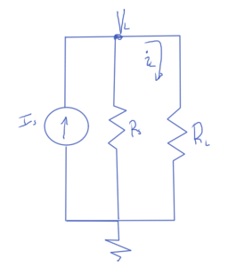
Now consider a current source and internal parallel resistance as sketched in fig. 3.

nortonEquivalentFig3

fig. 3. Current source configuration

There is only one nodal equation for this circuit

  1. \( -I_s + V_L Z_s + V_L Z_L = 0 \)

The load node voltage and current follows immediately

\begin{equation}\label{eqn:simpleNortonEquivalents:80}
V_L = \frac{I_s}{Z_L + Z_s}
\end{equation}
\begin{equation}\label{eqn:simpleNortonEquivalents:140}
i_L = V_L Z_L = \frac{Z_L I_s}{Z_L + Z_s}
\end{equation}

The goal is to find a value for \( I_L \) so that the voltage and currents at the load node match either of the first two voltage source configurations. It has been assumed that the desired parallel source resistance is the same as the series resistance in the voltage configurations. That was just a guess, but it ends up working out.

From \ref{eqn:simpleNortonEquivalents:80} and \ref{eqn:simpleNortonEquivalents:40} that equivalent current source can be found from

\begin{equation}\label{eqn:simpleNortonEquivalents:160}
V_L = V_s \frac{ R_L }{R_L + R_s} = \frac{I_s}{Z_L + Z_s},
\end{equation}

or

\begin{equation}\label{eqn:simpleNortonEquivalents:220}
I_s
=
V_s \frac{ R_L (Z_L + Z_s)}{R_L + R_s}
=
\frac{V_s}{R_S} \frac{ R_s R_L (Z_L + Z_s)}{R_L + R_s}
\end{equation}

\begin{equation}\label{eqn:simpleNortonEquivalents:240}
\boxed{
I_s
=
\frac{V_s}{R_S}.
}
\end{equation}

The load is expected to be the same through the load, and is

\begin{equation}\label{eqn:simpleNortonEquivalents:n}
i_L = V_L Z_L =
= V_s \frac{ R_L Z_L }{R_L + R_s}
= \frac{ V_s }{R_L + R_s},
\end{equation}

which matches \ref{eqn:simpleNortonEquivalents:100}.

Remarks

The equivalence of the series voltage source configurations with the parallel
current source configuration has been demonstrated with a resistive load. This
is a special case of the more general Norton’s theorem, as detailed in [2] and
[1] \S 5.1. Neither of those references prove the theorem. Norton’s theorem allows the equivalent current and resistance to be calculated without actually solving the system. Using that method, the parallel resistance equivalent follows by summing all the resistances in the source circuit with all the voltage sources shorted. Shorting the voltage sources in this source circuit results in the same configuration. It was seen directly in the two voltage source configurations that it did not matter, from the point of view of the external load, which sequence the internal series resistance and the voltage source were placed in did not matter. That becomes obvious with knowledge of Norton’s theorem, since shorting the voltage sources leaves just the single resistor in both cases.

References

[1] J.D. Irwin. Basic Engineering Circuit Analysis. Macillian, 1993.

[2] Wikipedia. Norton’s theorem — wikipedia, the free encyclopedia, 2014. URL https://en.wikipedia.org/w/index.php?title=Norton\%27s_theorem&oldid=629143825. [Online; accessed 1-November-2014].