Some basic keyboard operations on a mac

April 22, 2016 mac , , , , , , ,

I unpacked the macbook pro that I’ll be using for work, and quickly found myself slightly flummoxed by a combination of the keyboard and the os.  This blog post accumulates a running list of notes made as I learned my way around the new machine.

The list below was accumulated over time.  Here’s a recent popular science article that includes many of the shortcuts below, plus some other good ones.

Cut and Paste

The usual windows shortcuts work on a mac if you replace control with command:

copy: command-c
cut: command-x
paste: command-v

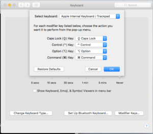
On a PC keyboard mapped mac-style (i.e. command=Alt, option=Windows, control=Ctrl):

Screen Shot 2016-05-12 at 10.08.21 AM
these would be Alt-c, Alt-x, and Alt-v respectively.

Navigation

right click: control-click, or two fingers simultaneously on the touchpad

page up/down: fn+arrow up/down

home: function left-arrow
end: function right-arrow

control-arrow (word skip in text editors): use option-arrow (Windows-arrow with a PC keyboard).

Some applications seem to use Alt-arrow (i.e. mac command-arrow)

command-tab switching to minimized window:

command-tab to select window.  hold option key, release command key.

trackpad tricks:

three finger swipe left/right.  This is like Windows control-tab switching but only between maximized applications.

“tab” switching between windows of the same application (i.e. Mathematica):

command-tilde (~)

Misc

delete in finder: command-delete

enter/exit fullscreen mode: command-control f

delete next character: Fn+delete

Terminal

undo accidental split of terminal (command d): command-shift d (command D)

function keys in terminal window: Fn+function-key

cycle between all terminal windows, even minimized ones: command left/right arrow

cycle between active windows: command `

equivalent to cmd explorer . : terminal: open .

equivalent to powershell open here:

System Preferences > Keyboard > Shortcuts > Services

Enable New Terminal at Folder.

There’s also a MacVim open service that you can use in Finder that I’d never noticed until trying this.

smooth scroll up/down

alt/option + command <arrow up/down>.  Not sure what keys to do this with on the mac keyboard itself, but with my windows keyboard this ends up being the page up/down keys.  Also doesn’t work properly in a screen session.

Moving Windows between displays

I found no builtin method to do Windows-Arrow like monitor switching, but the Sizeup freeware app seems to work nicely.

Cntl-Windows Arrows (i.e. mac Control-Options Arrows) does the window move for me with how I have my PC keyboard mapped.

There are also some split screen shortcuts:

^ \- % [arrow]

That work really nicely on a big thunderbolt monitor.

Virtual Desktops

On the mac keyboard, the virtual desktop manager control is available by pressing the F3 key (which shows three windows).

On a PC keyboard, use Ctrl-UpArrow

I’m using this to move any non-work windows to a separate space before starting work for the day.  This way I can’t be distracted by having a cool mathematics or physics puzzle left open and taunting.

This is also a way to move windows between multiple monitor displays.

PC keyboard

One nice thing about a PC keyboard is the function key mappings in Terminal might just work (without having to press Fn-Function-key).  That was true of my logitech keyboard, but not a Windows wireless keyboard (I still haven’t figured out how to get that wireless keyboard to work well with the mac).

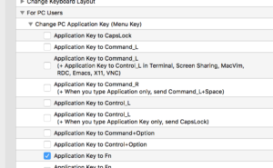
Can use Karabiner to map the Menu key to Fn. After installing select:

Screen Shot 2016-04-29 at 12.35.37 PM

Screenshot

snip: command shift 4

full: command shift 3

Browser

page down: spacebar

page up: shift spacebar

two figures up/down: scrolling

tab switching: option-cmd <- ->

new tab: cmd t

close tab: cmd w

Finder dialogue

Go to the parent directory: Command+up-arrow

Another way is to add a Path button to the finder using View -> Customize, as described in method 5 of the linked article.

Save as, to a different directory: Use the little sneaky triangle symbol in the file dialogue.

Safari

Copy a link: Link on the url tab, then Cmd+L ; Cmd+C

Variational principle with two by two symmetric matrix

March 12, 2016 math and physics play , ,

[Click here for a PDF of this post with nicer formatting]

I pulled [1], one of too many lonely Dover books, off my shelf and started reading the review chapter. It posed the following question, which I thought had an interesting subquestion.

Variational principle with two by two matrix.

Consider a \( 2 \times 2 \) real symmetric matrix operator \(\BO \), with an arbitrary normalized trial vector

\begin{equation}\label{eqn:variationalMatrix:20}
\Bc =
\begin{bmatrix}
\cos\theta \\
\sin\theta
\end{bmatrix}.
\end{equation}

The variational principle requires that minimum value of \( \omega(\theta) = \Bc^\dagger \BO \Bc \) is greater than or equal to the lowest eigenvalue. If that minimum value occurs at \( \omega(\theta_0) \), show that this is exactly equal to the lowest eigenvalue and explain why this is expected.

Why this is expected is the part of the question that I thought was interesting.

Finding the minimum.

If the operator representation is

\begin{equation}\label{eqn:variationalMatrix:40}
\BO =
\begin{bmatrix}
a & b \\
b & d
\end{bmatrix},
\end{equation}

then the variational product is

\begin{equation}\label{eqn:variationalMatrix:80}
\begin{aligned}
\omega(\theta)
&=
\begin{bmatrix}
\cos\theta & \sin\theta
\end{bmatrix}
\begin{bmatrix}
a & b \\
b & d
\end{bmatrix}
\begin{bmatrix}
\cos\theta \\
\sin\theta
\end{bmatrix} \\
&=
\begin{bmatrix}
\cos\theta & \sin\theta
\end{bmatrix}
\begin{bmatrix}
a \cos\theta + b \sin\theta \\
b \cos\theta + d \sin\theta
\end{bmatrix} \\
&=
a \cos^2\theta + 2 b \sin\theta \cos\theta
+ d \sin^2\theta \\
&=
a \cos^2\theta + b \sin( 2 \theta )
+ d \sin^2\theta.
\end{aligned}
\end{equation}

The minimum is given by

\begin{equation}\label{eqn:variationalMatrix:60}
\begin{aligned}
0
&=
\frac{d\omega}{d\theta} \\
&=
-2 a \sin\theta \cos\theta + 2 b \cos( 2 \theta )
+ 2 d \sin\theta \cos\theta \\
&=
2 b \cos( 2 \theta )
+ (d -a)\sin( 2 \theta )
\end{aligned}
,
\end{equation}

so the extreme values will be found at

\begin{equation}\label{eqn:variationalMatrix:100}
\tan(2\theta_0) = \frac{2 b}{a – d}.
\end{equation}

Solving for \( \cos(2\theta_0) \), with \( \alpha = 2b/(a-d) \), we have

\begin{equation}\label{eqn:variationalMatrix:120}
1 – \cos^2(2\theta) = \alpha^2 \cos^2(2 \theta),
\end{equation}

or

\begin{equation}\label{eqn:variationalMatrix:140}
\begin{aligned}
\cos^2(2\theta_0)
&= \frac{1}{1 + \alpha^2} \\
&= \frac{1}{1 + 4 b^2/(a-d)^2 } \\
&= \frac{(a-d)^2}{(a-d)^2 + 4 b^2 }.
\end{aligned}
\end{equation}

So,

\begin{equation}\label{eqn:variationalMatrix:200}
\begin{aligned}
\cos(2 \theta_0) &= \frac{ \pm (a-d) }{\sqrt{ (a-d)^2 + 4 b^2 }} \\
\sin(2 \theta_0) &= \frac{ \pm 2 b }{\sqrt{ (a-d)^2 + 4 b^2 }},
\end{aligned}
\end{equation}

Substituting this back into \( \omega(\theta_0) \) is a bit tedious.
I did it once on paper, then confirmed with Mathematica (quantumchemistry/twoByTwoSymmetricVariation.nb). The end result is

\begin{equation}\label{eqn:variationalMatrix:160}
\omega(\theta_0)
=
\inv{2} \lr{ a + d \pm \sqrt{ (a-d)^2 + 4 b^2 } }.
\end{equation}

The eigenvalues of the operator are given by

\begin{equation}\label{eqn:variationalMatrix:220}
\begin{aligned}
0
&= (a-\lambda)(d-\lambda) – b^2 \\
&= \lambda^2 – (a+d) \lambda + a d – b^2 \\
&= \lr{\lambda – \frac{a+d}{2}}^2 -\lr{ \frac{a+d}{2}}^2 + a d – b^2 \\
&= \lr{\lambda – \frac{a+d}{2}}^2 – \inv{4} \lr{ (a-d)^2 + 4 b^2 },
\end{aligned}
\end{equation}

so the eigenvalues are exactly the values \ref{eqn:variationalMatrix:160} as stated by the problem statement.

Why should this have been anticipated?

If the eigenvectors are \( \Be_1, \Be_2 \), the operator can be diagonalized as

\begin{equation}\label{eqn:variationalMatrix:240}
\BO = U D U^\T,
\end{equation}

where \( U = \begin{bmatrix} \Be_1 & \Be_2 \end{bmatrix} \), and \( D \) has the eigenvalues along the diagonal. The energy function \( \omega \) can now be written

\begin{equation}\label{eqn:variationalMatrix:260}
\begin{aligned}
\omega
&= \Bc^\T U D U^\T \Bc \\
&= (U^\T \Bc)^\T D U^\T \Bc.
\end{aligned}
\end{equation}

We can show that the transformed vector \( U^\T \Bc \) is still a unit vector

\begin{equation}\label{eqn:variationalMatrix:280}
\begin{aligned}
U^\T \Bc
&=
\begin{bmatrix}
\Be_1^\T \\
\Be_2^\T \\
\end{bmatrix}
\Bc \\
&=
\begin{bmatrix}
\Be_1^\T \Bc \\
\Be_2^\T \Bc \\
\end{bmatrix},
\end{aligned}
\end{equation}

so
\begin{equation}\label{eqn:variationalMatrix:300}
\begin{aligned}
\Abs{
U^\T \Bc
}^2
&=
\Bc^\T \Be_1
\Be_1^\T \Bc
+
\Bc^\T \Be_2
\Be_2^\T \Bc \\
&=
\Bc^\T \lr{ \Be_1 \Be_1^\T
+
\Be_2
\Be_2^\T } \Bc \\
&=
\Bc^\T \Bc \\
&= 1,
\end{aligned}
\end{equation}

so the transformed vector can be written as

\begin{equation}\label{eqn:variationalMatrix:320}
U^\T \Bc =
\begin{bmatrix}
\cos\phi \\
\sin\phi
\end{bmatrix},
\end{equation}

for some \( \phi \). With such a representation we have
\begin{equation}\label{eqn:variationalMatrix:340}
\begin{aligned}
\omega
&=
\begin{bmatrix}
\cos\phi & \sin\phi
\end{bmatrix}
\begin{bmatrix}
\lambda_1 & 0 \\
0 & \lambda_2
\end{bmatrix}
\begin{bmatrix}
\cos\phi \\
\sin\phi
\end{bmatrix} \\
&=
\begin{bmatrix}
\cos\phi & \sin\phi
\end{bmatrix}
\begin{bmatrix}
\lambda_1 \cos\phi \\
\lambda_2 \sin\phi
\end{bmatrix} \\
&=
\lambda_1 \cos^2\phi + \lambda_2 \sin^2\phi.
\end{aligned}
\end{equation}

This has it’s minimums where \( 0 = \sin(2 \phi)( \lambda_2 – \lambda_1 ) \). For the non-degenerate case, two zeros at \( \phi = n \pi/2 \) for integral \( n \). For \( \phi = 0, \pi/2 \), we have

\begin{equation}\label{eqn:variationalMatrix:360}
\Bc =
\begin{bmatrix}
1 \\
0
\end{bmatrix},
\begin{bmatrix}
0 \\
1
\end{bmatrix}.
\end{equation}

We see that the extreme values of \( \omega \) occur when the trial vectors \( \Bc \) are eigenvectors of the operator.

References

[1] Attila Szabo and Neil S Ostlund. Modern quantum chemistry: introduction to advanced electronic structure theory. Dover publications, 1989.

Did “Canada” stop bringing peace to Syria by bombing them?

March 10, 2016 Incoherent ramblings , , , , ,

March 10, 2016

Dear Prime Minister Trudeau,

My wife got caught up in the “hope and change” type propaganda associated with your campaign, but I was more cynical. I was, however, pleasantly surprised when you announced that Canada would no longer be bombing Syria. I would actually say that I was shocked and surprised that a Canadian politician had some sanity.

Needless to say, it wasn’t surprising to me that you later back-pedalled on this, and announced that “Canada” would continue to bomb Syria until Feb 22, 2016 [1, 2], apparently acting on the instructions of your handlers in Davos. The fact that this is done while simultaneously posing for photo ops with Syrian refugees and claiming that “Canada welcomes refugees” is particularly repugnant. My faith in the status quo of Canadian politics is nicely restored by your lack of action and backbone.

It is now well past Feb 22, but I have not seen any media suggesting that you have followed through on your watered down promise of less future belligerence. This could be a failing of the media, in particular, the CBC, which appears to be solidly in the pockets of armaments industry, reporting idiocy like “Most Canadians disagree” that we should continue to bring peace and solve the Syrian refugee outflux by bombing them [3]. Can you please confirm or deny whether you did limit “our” peacekeeping to one additional month of bombing.

Sincerely,

Peeter Joot

[1] http://www.cbc.ca/news/politics/isis-bombing-cf-18s-trudeau-milewskie-1.3416472
[2] http://www.cbc.ca/news/politics/justin-trudeau-canada-isis-fight-announcement-1.3438279
[3] http://www.cbc.ca/news/politics/canada-fighter-jets-isis-poll-1.3437288

A copy of this letter and any responses will be made available on the internet for public comment.

ECE1236H Microwave and Millimeter-Wave Techniques. Lecture: Continuum and other transformers. Taught by Prof. G.V. Eleftheriades

February 12, 2016 ece1236

[Click here for a PDF of this post with nicer formatting and figures] or [Click here for my notes compilation for this class]

Disclaimer

Peeter’s lecture notes from class. These may be incoherent and rough.

These are notes for the UofT course ECE1236H, Microwave and Millimeter-Wave
Techniques, taught by Prof. G.V. Eleftheriades, covering ch. 5 [1] content.

Continuum transformer

A non-discrete impedance matching transformation, as sketched in fig. 1, is also possible.

../../figures/ece1236/taperedLinesFig1: fig. 1. Tapered impedance matching.

\begin{equation}\label{eqn:continuumAndOtherTransformersCore:820}
\begin{aligned}
\Delta \Gamma
&= \frac{ (Z + \Delta Z) – Z }{(Z + \Delta Z) + Z} \\
&= \frac{\Delta Z}{2 Z}
\end{aligned}
\end{equation}

\begin{equation}\label{eqn:continuumAndOtherTransformersCore:840}
\Delta Z \rightarrow 0
\end{equation}

\begin{equation}\label{eqn:continuumAndOtherTransformersCore:860}
\begin{aligned}
d\Gamma
&= \frac{dZ}{2 Z} \\
&= \inv{2} \frac{d (\ln Z)}{dz} \\
&= \frac{Z_0}{Z} \frac{d (Z/Z_0)}{dz} \\
&= \frac{1}{Z} \frac{d Z}{dz}.
\end{aligned}
\end{equation}

Hence as we did for multisection transformers, associate \( \Delta \Gamma \) with \( e^{- 2j \beta z} \) as sketched in fig. 2.

../../figures/ece1236/taperedLinesFig2: fig. 2. Reflection coefficient over an interval

assuming small reflections (i.e. \( Z(z) \) is a slowly varying (adiabatic). Then

\begin{equation}\label{eqn:continuumAndOtherTransformersCore:920}
\begin{aligned}
\Gamma(\omega)
&= \int_0^L e^{ -2 j \beta z} d\Gamma \\
&= \inv{2}
\int_0^L e^{ -2 j \beta z} \frac{d (\ln Z)}{dz} dz
\end{aligned}
\end{equation}

This supplies the means to calculate the reflection coefficient for any impedance curve. As with the step impedance matching process, it is assumed that only first order reflections are of interest.

Exponential taper

Let
\begin{equation}\label{eqn:continuumAndOtherTransformersCore:620}
Z(z) = Z_0 e^{a z}, \qquad 0 < z < L \end{equation} subject to \begin{equation}\label{eqn:continuumAndOtherTransformersCore:640} \begin{aligned} Z(0) &= Z_0 \\ Z(L) &= Z_0 e^{a L} = Z_{\textrm{L}}, \end{aligned} \end{equation} which gives \begin{equation}\label{eqn:continuumAndOtherTransformersCore:660} \ln \frac{Z_{\textrm{L}}}{Z_0} = a L, \end{equation} or \begin{equation}\label{eqn:continuumAndOtherTransformersCore:680} a = \inv{L} \ln \frac{Z_{\textrm{L}}}{Z_0} \end{equation} Also \begin{equation}\label{eqn:continuumAndOtherTransformersCore:700} \frac{d}{dz} \ln \frac{Z_{\textrm{L}}}{Z_0} = \frac{d}{dz} (az) = a, \end{equation} Hence \begin{equation}\label{eqn:continuumAndOtherTransformersCore:740} \begin{aligned} \Gamma(\omega) &= \inv{2} \int_0^L e^{-2 j \beta z} \frac{d}{dz} \ln \frac{Z_{\textrm{L}}}{Z_0} dz \\ &= \frac{a}{2} \int_0^L e^{-2 j \beta z} dz \\ &= \frac{1}{2L} \ln \frac{Z_{\textrm{L}}}{Z_0} \evalrange{ \frac{e^{-2 j \beta z} }{ -2 j \beta} }{0}{L} \\ &= \frac{1}{2L \beta} \ln \frac{Z_{\textrm{L}}}{Z_0} \frac{ 1 - e^{-2 j \beta L} }{2 j} \\ &= \frac{1}{2} \ln \frac{Z_{\textrm{L}}}{Z_0} e^{-j \beta L} \frac{\sin( \beta L )}{\beta L}, \end{aligned} \end{equation} or \begin{equation}\label{eqn:continuumAndOtherTransformersCore:940} \Gamma(\omega) = \frac{1}{2} \ln \frac{Z_{\textrm{L}}}{Z_0} e^{-j \beta L} \textrm{sinc}( \beta L ). \end{equation}

  1. \( \beta \) is constant with \( Z \) varying: this is good only for TEM lines.
  2. \( \Abs{\Gamma} \) decreases with increasing length.
  3. An electrical length \( \beta L > \pi \), is required to minimize low frequency mismatch (\( L > \lambda/2\)).

This is sketched in fig. 3.

../../figures/ece1236/taperedLinesFig3: fig. 3. Exponential taper reflection coefficient.

Want:

\begin{equation}\label{eqn:continuumAndOtherTransformersCore:760}
\beta L = \pi,
\end{equation}

or
\begin{equation}\label{eqn:continuumAndOtherTransformersCore:780}
\frac{\omega_c}{v_\phi} L = \pi
\end{equation}

where \( \omega_c \) is the cutoff frequency. This gives

\begin{equation}\label{eqn:continuumAndOtherTransformersCore:800}
\omega_c = \frac{\pi v_\phi}{L}.
\end{equation}

Triangular Taper

\begin{equation}\label{eqn:continuumAndOtherTransformersCore:960}
Z(z) =
\left\{
\begin{array}{l l}
Z_0 e^{2(z/L)^2 \ln(Z_{\textrm{L}}/Z_0)} & \quad \mbox{\( 0 \le z \le L/2\)} \\
Z_0 e^{(4z/L – 2 z^2 – 1) \ln(Z_{\textrm{L}}/Z_0)} & \quad \mbox{\( L/2 \le z \le L\)} \\
\end{array}
\right.
\end{equation}

\begin{equation}\label{eqn:continuumAndOtherTransformersCore:980}
\frac{d}{dz} \ln (Z/Z_0) =
\left\{
\begin{array}{l l}
{(4z/L^2) \ln(Z_{\textrm{L}}/Z_0)} & \quad \mbox{\( 0 \le z \le L/2\)} \\
{(4/L – 4z/L^2) \ln(Z_{\textrm{L}}/Z_0)} & \quad \mbox{\( L/2 \le z \le L\)} \\
\end{array}
\right.
\end{equation}

In this case

\begin{equation}\label{eqn:continuumAndOtherTransformersCore:1000}
\Gamma(\omega) = \frac{1}{2} e^{-\beta L} \ln \frac{Z_{\textrm{L}}}{Z_0} e^{-j \beta L} \textrm{sinc}^2( \beta L/2 ).
\end{equation}

Compared to the exponential taper \( \textrm{sinc}( \beta L ) \) for the \( \beta L > 2 \pi \) the peaks of \( \Abs{\Gamma} \) are lower, but the first null occurs at \( \beta L = 2 \pi \) whereas for the exponential taper it occurs at \( \beta L = \pi \). This is sketched in fig. 4. The price to pay for this is that the zero is at \( 2 \pi \) so we have to make it twice as long to get the ripple down.

../../figures/ece1236/taperedLinesFig4: fig. 4. Triangular taper impedance curve.

Klopfenstein Taper

For a given taper length \( L \), the Klopfenstein taper is optimum in the sense that the reflection coefficient in the passband is minimum. Alternatively, for a given minimum reflection coefficient in the passband, the Klopfenstein taper yields the shortest length \( L \).

Definition:

\begin{equation}\label{eqn:continuumAndOtherTransformersCore:1020}
\ln Z = \inv{2} \ln (Z_0 Z_{\textrm{L}}) + \frac{\Gamma_0}{\cosh A} A^2 \phi(2 z/L -1, A), \qquad 0 \le z \le L,
\end{equation}

where

\begin{equation}\label{eqn:continuumAndOtherTransformersCore:1040}
\phi(x, A) = \int_0^x \frac{I_1(A\sqrt{1 – y^2})}{A \sqrt{1 – y^2}} dy, \qquad \Abs{x} \le 1.
\end{equation}

Here \( I_1(x) \) is the modified Bessel function. Note that
\begin{equation}\label{eqn:continuumAndOtherTransformersCore:1060}
\begin{aligned}
\phi(0, A) &= 0 \\
\phi(x, 0) &= x/2 \\
\phi(1, A) &= \frac{\cosh A – 1}{A^2}
\end{aligned}
\end{equation}

The resulting reflection coefficient is

\begin{equation}\label{eqn:continuumAndOtherTransformersCore:1080}
\Gamma(\omega)
=
\left\{
\begin{array}{l l}
\Gamma_0 e^{-j \beta L} \frac{\cos\sqrt{(\beta L)^2 – A^2}}{\cosh A} & \quad \mbox{\( \beta L > A \)} \\
\Gamma_0 e^{-j \beta L} \frac{\cos\sqrt{A^2 – (\beta L)^2 }}{\cosh A} & \quad \mbox{\( \beta L < A \)} \\ \end{array} \right., \end{equation} where as usual \begin{equation}\label{eqn:continuumAndOtherTransformersCore:1100} \Gamma_0 = \frac{Z_{\textrm{L}} - Z_0}{Z_{\textrm{L}} + Z_0} \approx \inv{2} \ln (Z_{\textrm{L}}/Z_0). \end{equation} The passband is defined by \( \beta L \ge A \) and the maximum ripple in the passband is \begin{equation}\label{eqn:continuumAndOtherTransformersCore:1120} \Gamma_m = \frac{\Gamma_0}{\cosh A}. \end{equation}

Example

Design a triangular taper, an exponential taper, and a Klopfenstein taper (with \( \Gamma_m = 0.02 \) ) to match a \( 50 \Omega \) load to a \( 100 \Omega \) line.

  • Triangular taper:

    \begin{equation}\label{eqn:continuumAndOtherTransformersCore:1140}
    Z(z) =
    \left\{
    \begin{array}{l l}
    Z_0 e^{ 2(z/L)^2 \ln Z_{\textrm{L}}/Z_0 } & \quad \mbox{\( 0 \le z \le L/2\)} \\
    Z_0 e^{ (4 z/L – 2 z^2/L^2 – 1)\ln Z_{\textrm{L}}/Z_0 } & \quad \mbox{\( L/2 \ge z \ge L \)}
    \end{array}
    \right.
    \end{equation}

    The resulting \( \Gamma \) is

    \begin{equation}\label{eqn:continuumAndOtherTransformersCore:1160}
    \Abs{\Gamma} = \inv{2} \ln (Z_{\textrm{L}}/Z_0) \textrm{sinc}^2\lr{ \beta L/2 }.
    \end{equation}

  • Exponential taper:

    \begin{equation}\label{eqn:continuumAndOtherTransformersCore:1180}
    \begin{aligned}
    Z(z) &= Z_0 e^{a z}, \qquad 0 \le z \le L \\
    a &= \inv{L} \ln (Z_{\textrm{L}}/Z_0) = \frac{0.693}{L} \\
    \Abs{\Gamma} &= \inv{2} \ln (Z_{\textrm{L}}/Z_0) \textrm{sinc}( \beta L )
    \end{aligned}
    \end{equation}

  • Klopfenstein taper:
    \begin{equation}\label{eqn:continuumAndOtherTransformersCore:1200}
    \begin{aligned}
    Z(z) &= \inv{2} \ln (Z_{\textrm{L}}/Z_0) = 0.346 \\
    A &= \cosh^{-1}\lr{ \frac{\Gamma_0}{\Gamma_m}} = \cosh^{-1}\lr{ \frac{0.346}{0.02}} = 3.543 \\
    \Abs{\Gamma} &= \Gamma_0 \frac{\cos\sqrt{(\beta L)^2 – A^2}}{\cosh A},
    \end{aligned}
    \end{equation}

    The passband \( \beta L > A = 3.543 = 1.13 \pi \). The impedance \( Z(z) \) must be evaluated numerically.

To illustrate some of the differences, we are referred to fig. 5.21 [1]. It is noted that

  1. The exponential taper has the lowest cutoff frequency \( \beta L = \pi \). Then is the Klopfenstein taper which is close \( \beta L = 1.13 \pi \). Last is the triangular with \( \beta L = 2 \pi \).
  2. The Klopfenstein taper has the lowest \( \Abs{\Gamma} \) in the passband and meets the spec of \( \Gamma_m = 0.02 \). The worst \( \Abs{\Gamma} \) in the passband is from the exponential taper and the triangular ripple is between the two others.

References

[1] David M Pozar. Microwave engineering. John Wiley & Sons, 2009.

ECE1236H Microwave and Millimeter-Wave Techniques. Lecture 7: Multisection quarter-wavelength transformers. Taught by Prof. G.V. Eleftheriades

February 11, 2016 ece1236 , , , , , , ,

[Click here for a PDF of this post with nicer formatting] or [Click here for my notes compilation for this class]

Disclaimer

Peeter’s lecture notes from class. These may be incoherent and rough.

These are notes for the UofT course ECE1236H, Microwave and Millimeter-Wave Techniques, taught by Prof. G.V. Eleftheriades, covering ch 5. [3] content.

Terminology review

\begin{equation}\label{eqn:uwavesDeck7MultisectionTransformersCore:20}
Z_{\textrm{in}} = R + j X
\end{equation}
\begin{equation}\label{eqn:uwavesDeck7MultisectionTransformersCore:40}
Y_{\textrm{in}} = G + j B
\end{equation}

  • \( Z_{\textrm{in}} \) : impedance
  • \( R \) : resistance
  • \( X \) : reactance
  • \( Y_{\textrm{in}} \) : admittance
  • \( G \) : conductance
  • \( B \) : susceptance

Apparently this notation goes all the way back to Heavyside!

Multisection transformers

Using a transformation of the form fig. 1 it is possible to optimize for maximum power delivery, using for example a matching transformation \( Z_{\textrm{in}} = Z_1^2/R_{\textrm{L}} = Z_0\), or \( Z_1 = \sqrt{R_{\textrm{L}} Z_0} \). Unfortunately, such a transformation does not allow any control over the bandwidth. This results in a pinched frequency response for which the standard solution is to add more steps as sketched in fig. 2.

../../figures/ece1236/Feb10Fig2: fig. 2. Pinched frequency response.
../../figures/ece1236/deck7Fig1: fig. 3. Single and multiple stage impedance matching.

This can be implemented in electronics, or potentially geometrically as in this sketch of a microwave stripline transformer implementation fig. 3.

../../figures/ece1236/deck7Fig3: fig. 3. Stripline implementation of staged impedance matching.

To find a multistep transformation algebraically can be hard, but it is easy to do on a Smith chart. The rule of thumb is that we want to stay near the center of the chart with each transformation.

There is however, a closed form method of calculating a specific sort of multisection transformation that is algebraically tractable. That method uses a chain of \( \lambda/4 \) transformers to increase the bandwidth as sketched in fig. 4.

../../figures/ece1236/deck7Fig4: fig. 4. Multiple \( \lambda/4 \) transformers.

The total reflection coefficient can be approximated to first order by summing the reflections at each stage (without considering there may be other internal reflections of transmitted field components). Algebraically that is

\begin{equation}\label{eqn:uwavesDeck7MultisectionTransformersCore:60}
\Gamma(\Theta) \approx \Gamma_0
+ \Gamma_1 e^{-2 j \Theta} +
+ \Gamma_2 e^{-4 j \Theta} + \cdots
+ \Gamma_N e^{-2 N j \Theta},
\end{equation}

where

\begin{equation}\label{eqn:uwavesDeck7MultisectionTransformersCore:80}
\Gamma_n = \frac{Z_{n+1} – Z_n}{Z_{n+1} + Z_n}
\end{equation}

Why? Consider reflections at the Z_1, Z_2 interface as sketched in fig. 5.

../../figures/ece1236/deck7Fig5: fig. 5. Single stage of multiple \( \lambda/4\) transformers.

Assuming small reflections, where \( \Abs{\Gamma} \ll 1 \) then \( T = 1 + \Gamma \approx 1 \). Here

\begin{equation}\label{eqn:uwavesDeck7MultisectionTransformersCore:100}
\begin{aligned}
\Theta
&= \beta l \\
&= \frac{2 \pi}{\lambda} \frac{\lambda}{4} \\
&= \frac{\pi}{2}.
\end{aligned}
\end{equation}

at the design frequency \( \omega_0 \). We assume that \( Z_n \) are either monotonically increasing if \( R_{\textrm{L}} > Z_0 \), or decreasing if \( R_{\textrm{L}} < Z_0 \).

Binomial multisection transformers

Let

\begin{equation}\label{eqn:uwavesDeck7MultisectionTransformersCore:120}
\Gamma(\Theta) = A \lr{ 1 + e^{-2 j \Theta} }^N
\end{equation}

This type of a response is maximally flat, and is plotted in fig. 1.
../../figures/ece1236/multitransformerFig1: fig. 1. Binomial transformer.

The absolute value of the reflection coefficient is

\begin{equation}\label{eqn:uwavesDeck7MultisectionTransformersCore:160}
\begin{aligned}
\Abs{\Gamma(\Theta)}
&=
\Abs{A} \lr{ e^{j \Theta} + e^{- j \Theta} }^N \\
&=
2^N \Abs{A} \cos^N\Theta.
\end{aligned}
\end{equation}

When \( \Theta = \pi/2 \) this is clearly zero. It’s derivatives are

\begin{equation}\label{eqn:uwavesDeck7MultisectionTransformersCore:180}
\begin{aligned}
\frac{d \Abs{\Gamma}}{d\Theta} &= -N \cos^{N-1} \Theta \sin\Theta \\
\frac{d^2 \Abs{\Gamma}}{d\Theta^2} &= -N \cos^{N-1} \Theta \cos\Theta N(N-1) \cos^{N-2} \Theta \sin\Theta \\
\frac{d^3 \Abs{\Gamma}}{d\Theta^3} &= \cdots
\end{aligned}
\end{equation}

There is a \( \cos^{N-k} \) term for all derivatives \( d^k/d\Theta^k \) where \( k \le N-1 \), so for an N-section transformer

\begin{equation}\label{eqn:uwavesDeck7MultisectionTransformersCore:140}
\frac{d^n}{d\Theta^n} \Abs{\Gamma(\Theta)}_{\omega_0} = 0,
\end{equation}

for \( n = 1, 2, \cdots, N-1 \). The constant \( A \) is determined by the limit \( \Theta \rightarrow 0 \), so

\begin{equation}\label{eqn:uwavesDeck7MultisectionTransformersCore:200}
\Gamma(0) = 2^N A = \frac{Z_{\textrm{L}} – Z_0}{Z_{\textrm{L}} + Z_0},
\end{equation}

because the various \( \Theta \) sections become DC wires when the segment length goes to zero. This gives

\begin{equation}\label{eqn:uwavesDeck7MultisectionTransformersCore:220}
\boxed{
A = 2^{-N} \frac{Z_{\textrm{L}} – Z_0}{Z_{\textrm{L}} + Z_0}.
}
\end{equation}

The reflection coefficient can now be expanded using the binomial theorem

\begin{equation}\label{eqn:uwavesDeck7MultisectionTransformersCore:240}
\begin{aligned}
\Gamma(\Theta)
&= A \lr{ 1 + e^{ 2 j \Theta } }^N \\
&= \sum_{k = 0}^N \binom{N}{k} e^{ -2 j k \Theta}
\end{aligned}
\end{equation}

Recall that

\begin{equation}\label{eqn:uwavesDeck7MultisectionTransformersCore:260}
\binom{N}{k} = \frac{N!}{k! (N-k)!},
\end{equation}

providing a symmetric set of values

\begin{equation}\label{eqn:uwavesDeck7MultisectionTransformersCore:280}
\begin{aligned}
\binom{N}{1} &= \binom{N}{N} = 1 \\
\binom{N}{1} &= \binom{N}{N-1} = N \\
\binom{N}{k} &= \binom{N}{N-k}.
\end{aligned}
\end{equation}

Equating \ref{eqn:uwavesDeck7MultisectionTransformersCore:240} with \ref{eqn:uwavesDeck7MultisectionTransformersCore:60} we have

\begin{equation}\label{eqn:uwavesDeck7MultisectionTransformersCore:300}
\boxed{
\Gamma_k = A \binom{N}{k}.
}
\end{equation}

Approximation for \( Z_k \)

From [1] (4.6.4), a log series expansion valid for all \( z \) is

\begin{equation}\label{eqn:uwavesDeck7MultisectionTransformersCore:320}
\ln z = \sum_{k = 0}^\infty \inv{2 k + 1} \lr{ \frac{ z – 1 }{z + 1} }^{2k + 1},
\end{equation}

so for \( x \) near unity a first order approximation of a logarithm is

\begin{equation}\label{eqn:uwavesDeck7MultisectionTransformersCore:340}
\ln x \approx 2 \frac{x -1}{x+1}.
\end{equation}

Assuming that \( Z_{k+1}/Z_k \) is near unity we have

\begin{equation}\label{eqn:uwavesDeck7MultisectionTransformersCore:360}
\begin{aligned}
\inv{2} \ln \frac{Z_{k+1}}{Z_k}
&\approx
\frac{ \frac{Z_{k+1}}{Z_k} – 1 }{\frac{Z_{k+1}}{Z_k} + 1} \\
&=
\frac{ Z_{k+1} – Z_k }{Z_{k+1} + Z_k} \\
&=
\Gamma_k.
\end{aligned}
\end{equation}

Using this approximation, we get

\begin{equation}\label{eqn:uwavesDeck7MultisectionTransformersCore:380}
\begin{aligned}
\ln \frac{Z_{k+1}}{Z_k}
&\approx
2 \Gamma_k \\
&= 2 A \binom{N}{k} \\
&= 2 \lr{2^{-N}} \binom{N}{k} \frac{Z_{\textrm{L}} – Z_0}{Z_{\textrm{L}} + Z_0} \\
&\approx
2^{-N} \binom{N}{k} \ln \frac{Z_{\textrm{L}}}{Z_0},
\end{aligned}
\end{equation}

I asked what business do we have in assuming that \( Z_{\textrm{L}}/Z_0 \) is near unity? The answer was that it isn’t but surprisingly it works out well enough despite that. As an example, consider \( Z_0 = 100 \Omega \) and \( R_{\textrm{L}} = 50 \Omega \). The exact expression

\begin{equation}\label{eqn:uwavesDeck7MultisectionTransformersCore:880}
\begin{aligned}
\frac{Z_{\textrm{L}} – Z_0}{Z_{\textrm{L}} + Z_0}
&= \frac{100-50}{100+50} \\
&= -0.333,
\end{aligned}
\end{equation}

whereas
\begin{equation}\label{eqn:uwavesDeck7MultisectionTransformersCore:900}
\inv{2} \ln \frac{Z_{\textrm{L}}}{Z_0} = -0.3466,
\end{equation}

which is pretty close after all.

Regardless of whether or not that last approximation is used, one can proceed iteratively to \( Z_{k+1} \) starting with \( k = 0 \).

Bandwidth

To evaluate the bandwidth, let \( \Gamma_{\mathrm{m}} \) be the maximum tolerable reflection coefficient over the passband, as sketched in fig. 6.

../../figures/ece1236/deck7Fig6: fig. 6. Max tolerable reflection.

That is

\begin{equation}\label{eqn:uwavesDeck7MultisectionTransformersCore:400}
\begin{aligned}
\Gamma_m
&= 2^N \Abs{A} \Abs{\cos \Theta_m }^N \\
&= 2^N \Abs{A} \cos^N \Theta_m,
\end{aligned}
\end{equation}

for \( \Theta_m < \pi/2 \). Then \begin{equation}\label{eqn:uwavesDeck7MultisectionTransformersCore:420} \Theta_m = \arccos\lr{ \inv{2} \lr{ \frac{\Gamma_{\mathrm{m}}}{\Abs{A}}}^{1/N} } \end{equation} The relative width of the interval is \begin{equation}\label{eqn:uwavesDeck7MultisectionTransformersCore:440} \begin{aligned} \frac{\Delta f_{\mathrm{max}}}{f_0} &= \frac{\Delta \Theta_{\mathrm{max}}}{\Theta_0} \\ &= \frac{2 (\Theta_0 - \Theta_{\mathrm{max}}}{\Theta_0} \\ &= 2 - \frac{2 \Theta_{\mathrm{max}}}{\Theta_0} \\ &= 2 - \frac{4 \Theta_{\mathrm{max}}}{\pi} \\ &= 2 - \frac{4 }{\pi} \arccos\lr{ \inv{2} \lr{ \frac{\Gamma_{\mathrm{max}}}{\Abs{A}}}^{1/N} }. \end{aligned} \end{equation}

Example

Design a 3-section binomial transformer to match \( R_{\textrm{L}} = 50 \Omega \) to a line \( Z_0 = 100 \Omega \). Calculate the BW based on a maximum \( \Gamma_{\textrm{m}} = 0.05 \).

Solution

The scaling factor
\begin{equation}\label{eqn:uwavesDeck7MultisectionTransformersCore:460}
\begin{aligned}
A
&= 2^{-N} \frac{Z_{\textrm{L}} – L_0}{Z_{\textrm{L}} + Z_0} \\
&\approx
\inv{2^{N+1}} \ln \frac{Z_{\textrm{L}}}{Z_0} \\
&= -0.0433
\end{aligned}
\end{equation}

Now use

\begin{equation}\label{eqn:uwavesDeck7MultisectionTransformersCore:940}
\ln \frac{Z_{n+1}}{Z_n}
\approx 2^{-N} \binom{N}{n} \ln \frac{R_{\textrm{L}}}{Z_0},
\end{equation}

starting from

  • \( n = 0 \).

    \begin{equation}\label{eqn:uwavesDeck7MultisectionTransformersCore:480}
    \ln \frac{Z_{1}}{Z_0} \approx 2^{-3} \binom{3}{0} \ln \frac{R_{\textrm{L}}}{Z_0},
    \end{equation}

    or
    \begin{equation}\label{eqn:uwavesDeck7MultisectionTransformersCore:500}
    \begin{aligned}
    \ln Z_{1}
    &= \ln Z_0 + 2^{-3} \binom{3}{0} \ln \frac{R_{\textrm{L}}}{Z_0} \\
    &= \ln 100 + 2^{-3} (1) \ln 0.5 \\
    &= 4.518,
    \end{aligned}
    \end{equation}

    so
    \begin{equation}\label{eqn:uwavesDeck7MultisectionTransformersCore:520}
    Z_1 = 91.7 \Omega
    \end{equation}

  • \( n = 1 \)

    \begin{equation}\label{eqn:uwavesDeck7MultisectionTransformersCore:540}
    \ln Z_{2}
    = \ln Z_1 + 2^{-3} \binom{3}{1} \ln \frac{50}{100} = 4.26
    \end{equation}

    so
    \begin{equation}\label{eqn:uwavesDeck7MultisectionTransformersCore:560}
    Z_2 = 70.7 \Omega
    \end{equation}

  • \( n = 2 \)

    \begin{equation}\label{eqn:uwavesDeck7MultisectionTransformersCore:580}
    \ln Z_{3} = \ln Z_2 + 2^{-3} \binom{3}{2} \ln \frac{50}{100} = 4.0,
    \end{equation}

    so

    \begin{equation}\label{eqn:uwavesDeck7MultisectionTransformersCore:600}
    Z_3 = 54.5 \Omega.
    \end{equation}

With the fractional BW for \( \Gamma_m = 0.05 \), where \( 10 \log_{10} \Abs{\Gamma_m}^2 = -26 \) dB}.

\begin{equation}\label{eqn:uwavesDeck7MultisectionTransformersCore:920}
\begin{aligned}
\frac{\Delta f}{f_0}
&\approx
2 – \frac{4}{\pi} \arccos\lr{ \inv{2} \lr{ \frac{\Gamma_m}{\Abs{A}} }^{1/N} } \\
&=
2 – \frac{4}{\pi} \arccos\lr{ \inv{2} \lr{ \frac{0.05}{0.0433} }^{1/3} } \\
&= 0.7
\end{aligned}
\end{equation}

At \( 2 \) GHz, \( BW = 0.7 \) (70%), or \( 1.4 \) GHz, which is the range \( [2.3,2.7] \) GHz, whereas a single \( \lambda/4 \) transformer \( Z_T = \sqrt{ (100)(50) } = 70.7 \Omega \) yields a BW of just \( 0.36 \) GHz (18%).

References

[1] DLMF. NIST Digital Library of Mathematical Functions. https://dlmf.nist.gov/, Release 1.0.10 of 2015-08-07. URL https://dlmf.nist.gov/. Online companion to Olver:2010:NHMF.

[2] F. W. J. Olver, D. W. Lozier, R. F. Boisvert, and C. W. Clark, editors. NIST Handbook of Mathematical Functions. Cambridge University Press, New York, NY, 2010. Print companion to NIST:DLMF.

[3] David M Pozar. Microwave engineering. John Wiley & Sons, 2009.