Mathematica

Electric field due to spherical shell

August 24, 2016 math and physics play , ,

[Click here for a PDF of this post with nicer formatting]

Here’s a problem (2.7) from [1], to calculate the field due to a spherical shell. The field is

\begin{equation}\label{eqn:griffithsEM2_7:20}
\BE = \frac{\sigma}{4 \pi \epsilon_0} \int \frac{(\Br – \Br’)}{\Abs{\Br – \Br’}^3} da’,
\end{equation}

where \( \Br’ \) is the position to the area element on the shell. For the test position, let \( \Br = z \Be_3 \). We need to parameterize the area integral. A complex-number like geometric algebra representation works nicely.

\begin{equation}\label{eqn:griffithsEM2_7:40}
\begin{aligned}
\Br’
&= R \lr{ \sin\theta \cos\phi, \sin\theta \sin\phi, \cos\theta } \\
&= R \lr{ \Be_1 \sin\theta \lr{ \cos\phi + \Be_1 \Be_2 \sin\phi } + \Be_3 \cos\theta } \\
&= R \lr{ \Be_1 \sin\theta e^{i\phi} + \Be_3 \cos\theta }.
\end{aligned}
\end{equation}

Here \( i = \Be_1 \Be_2 \) has been used to represent to horizontal rotation plane.

The difference in position between the test vector and area-element is

\begin{equation}\label{eqn:griffithsEM2_7:60}
\Br – \Br’
= \Be_3 \lr{ z – R \cos\theta } – R \Be_1 \sin\theta e^{i \phi},
\end{equation}

with an absolute squared length of

\begin{equation}\label{eqn:griffithsEM2_7:80}
\begin{aligned}
\Abs{\Br – \Br’ }^2
&= \lr{ z – R \cos\theta }^2 + R^2 \sin^2\theta \\
&= z^2 + R^2 – 2 z R \cos\theta.
\end{aligned}
\end{equation}

As a side note, this is a kind of fun way to prove the old “cosine-law” identity. With that done, the field integral can now be expressed explicitly

\begin{equation}\label{eqn:griffithsEM2_7:100}
\begin{aligned}
\BE
&= \frac{\sigma}{4 \pi \epsilon_0} \int_{\phi = 0}^{2\pi} \int_{\theta = 0}^\pi R^2 \sin\theta d\theta d\phi
\frac{\Be_3 \lr{ z – R \cos\theta } – R \Be_1 \sin\theta e^{i \phi}}
{
\lr{z^2 + R^2 – 2 z R \cos\theta}^{3/2}
} \\
&= \frac{2 \pi R^2 \sigma \Be_3}{4 \pi \epsilon_0} \int_{\theta = 0}^\pi \sin\theta d\theta
\frac{z – R \cos\theta}
{
\lr{z^2 + R^2 – 2 z R \cos\theta}^{3/2}
} \\
&= \frac{2 \pi R^2 \sigma \Be_3}{4 \pi \epsilon_0} \int_{\theta = 0}^\pi \sin\theta d\theta
\frac{ R( z/R – \cos\theta) }
{
(R^2)^{3/2} \lr{ (z/R)^2 + 1 – 2 (z/R) \cos\theta}^{3/2}
} \\
&= \frac{\sigma \Be_3}{2 \epsilon_0} \int_{u = -1}^{1} du
\frac{ z/R – u}
{
\lr{1 + (z/R)^2 – 2 (z/R) u}^{3/2}
}.
\end{aligned}
\end{equation}

Observe that all the azimuthal contributions get killed. We expect that due to the symmetry of the problem. We are left with an integral that submits to Mathematica, but doesn’t look fun to attempt manually. Specifically

\begin{equation}\label{eqn:griffithsEM2_7:120}
\int_{-1}^1 \frac{a-u}{\lr{1 + a^2 – 2 a u}^{3/2}} du
=
\left\{
\begin{array}{l l}
\frac{2}{a^2} & \quad \mbox{if \( a > 1 \) } \\
0 & \quad \mbox{if \( a < 1 \) } \end{array} \right., \end{equation} so \begin{equation}\label{eqn:griffithsEM2_7:140} \boxed{ \BE = \left\{ \begin{array}{l l} \frac{\sigma (R/z)^2 \Be_3}{\epsilon_0} & \quad \mbox{if \( z > R \) } \\
0 & \quad \mbox{if \( z < R \) } \end{array} \right. } \end{equation} In the problem, it is pointed out to be careful of the sign when evaluating \( \sqrt{ R^2 + z^2 - 2 R z } \), however, I don't see where that is even useful?

References

[1] David Jeffrey Griffiths and Reed College. Introduction to electrodynamics. Prentice hall Upper Saddle River, NJ, 3rd edition, 1999.
Expectation of spherically symmetric 3D potential derivative

December 14, 2015 phy1520 , , , , , ,

[Click here for a PDF of this post with nicer formatting]

Q: [1] pr 5.16

For a particle in a spherically symmetric potential \( V(r) \) show that

\begin{equation}\label{eqn:symmetricPotentialDerivativeExpectation:20}
\Abs{\psi(0)}^2 = \frac{m}{2 \pi \Hbar^2} \expectation{ \frac{dV}{dr} },
\end{equation}

for all s-states, ground or excited.

Then show this is the case for the 3D SHO and hydrogen wave functions.

A:

The text works a problem that looks similar to this by considering the commutator of an operator \( A \), later set to \( A = p_r = -i \Hbar \PDi{r}{} \) the radial momentum operator. First it is noted that

\begin{equation}\label{eqn:symmetricPotentialDerivativeExpectation:40}
0 = \bra{nlm} \antisymmetric{H}{A} \ket{nlm},
\end{equation}

since \( H \) operating to either the right or the left is the energy eigenvalue \( E_n \). Next it appears the author uses an angular momentum factoring of the squared momentum operator. Looking earlier in the text that factoring is found to be

\begin{equation}\label{eqn:symmetricPotentialDerivativeExpectation:60}
\frac{\Bp^2}{2m}
= \inv{2 m r^2} \BL^2 – \frac{\Hbar^2}{2m} \lr{ \PDSq{r}{} + \frac{2}{r} \PD{r}{} }.
\end{equation}

With
\begin{equation}\label{eqn:symmetricPotentialDerivativeExpectation:80}
R = – \frac{\Hbar^2}{2m} \lr{ \PDSq{r}{} + \frac{2}{r} \PD{r}{} }.
\end{equation}

we have

\begin{equation}\label{eqn:symmetricPotentialDerivativeExpectation:100}
\begin{aligned}
0
&= \bra{nlm} \antisymmetric{H}{p_r} \ket{nlm} \\
&= \bra{nlm} \antisymmetric{\frac{\Bp^2}{2m} + V(r)}{p_r} \ket{nlm} \\
&= \bra{nlm} \antisymmetric{\inv{2 m r^2} \BL^2 + R + V(r)}{p_r} \ket{nlm} \\
&= \bra{nlm} \antisymmetric{\frac{-\Hbar^2 l (l+1)}{2 m r^2} + R + V(r)}{p_r} \ket{nlm}.
\end{aligned}
\end{equation}

Let’s consider the commutator of each term separately. First

\begin{equation}\label{eqn:symmetricPotentialDerivativeExpectation:120}
\begin{aligned}
\antisymmetric{V}{p_r} \psi
&=
V p_r \psi

p_r V \psi \\
&=
V p_r \psi

(p_r V) \psi

V p_r \psi \\
&=

(p_r V) \psi \\
&=
i \Hbar \PD{r}{V} \psi.
\end{aligned}
\end{equation}

Setting \( V(r) = 1/r^2 \), we also have

\begin{equation}\label{eqn:symmetricPotentialDerivativeExpectation:160}
\antisymmetric{\inv{r^2}}{p_r} \psi
=
-\frac{2 i \Hbar}{r^3} \psi.
\end{equation}

Finally
\begin{equation}\label{eqn:symmetricPotentialDerivativeExpectation:180}
\begin{aligned}
\antisymmetric{\PDSq{r}{} + \frac{2}{r} \PD{r}{} }{ \PD{r}{}}
&=
\lr{ \partial_{rr} + \frac{2}{r} \partial_r } \partial_r

\partial_r \lr{ \partial_{rr} + \frac{2}{r} \partial_r } \\
&=
\partial_{rrr} + \frac{2}{r} \partial_{rr}

\lr{
\partial_{rrr} -\frac{2}{r^2} \partial_r + \frac{2}{r} \partial_{rr}
} \\
&=
-\frac{2}{r^2} \partial_r,
\end{aligned}
\end{equation}

so
\begin{equation}\label{eqn:symmetricPotentialDerivativeExpectation:200}
\antisymmetric{R}{p_r}
=-\frac{2}{r^2} \frac{-\Hbar^2}{2m} p_r
=\frac{\Hbar^2}{m r^2} p_r.
\end{equation}

Putting all the pieces back together, we’ve got
\begin{equation}\label{eqn:symmetricPotentialDerivativeExpectation:220}
\begin{aligned}
0
&= \bra{nlm} \antisymmetric{\frac{-\Hbar^2 l (l+1)}{2 m r^2} + R + V(r)}{p_r} \ket{nlm} \\
&=
i \Hbar
\bra{nlm} \lr{
\frac{\Hbar^2 l (l+1)}{m r^3} – \frac{i\Hbar}{m r^2} p_r +
\PD{r}{V}
}
\ket{nlm}.
\end{aligned}
\end{equation}

Since s-states are those for which \( l = 0 \), this means

\begin{equation}\label{eqn:symmetricPotentialDerivativeExpectation:240}
\begin{aligned}
\expectation{\PD{r}{V}}
&= \frac{i\Hbar}{m } \expectation{ \inv{r^2} p_r } \\
&= \frac{\Hbar^2}{m } \expectation{ \inv{r^2} \PD{r}{} } \\
&= \frac{\Hbar^2}{m } \int_0^\infty dr \int_0^\pi d\theta \int_0^{2 \pi} d\phi r^2 \sin\theta \psi^\conj(r,\theta, \phi) \inv{r^2} \PD{r}{\psi(r,\theta,\phi)}.
\end{aligned}
\end{equation}

Since s-states are spherically symmetric, this is
\begin{equation}\label{eqn:symmetricPotentialDerivativeExpectation:260}
\expectation{\PD{r}{V}}
= \frac{4 \pi \Hbar^2}{m } \int_0^\infty dr \psi^\conj \PD{r}{\psi}.
\end{equation}

That integral is

\begin{equation}\label{eqn:symmetricPotentialDerivativeExpectation:280}
\int_0^\infty dr \psi^\conj \PD{r}{\psi}
=
\evalrange{\Abs{\psi}^2}{0}{\infty} – \int_0^\infty dr \PD{r}{\psi^\conj} \psi.
\end{equation}

With the hydrogen atom, our radial wave functions are real valued. It’s reasonable to assume that we can do the same for other real-valued spherical potentials. If that is the case, we have

\begin{equation}\label{eqn:symmetricPotentialDerivativeExpectation:300}
2 \int_0^\infty dr \psi^\conj \PD{r}{\psi}
=
\Abs{\psi(0)}^2,
\end{equation}

and

\begin{equation}\label{eqn:symmetricPotentialDerivativeExpectation:320}
\boxed{
\expectation{\PD{r}{V}}
= \frac{2 \pi \Hbar^2}{m } \Abs{\psi(0)}^2,
}
\end{equation}

which completes this part of the problem.

A: show this is the case for the 3D SHO and hydrogen wave functions

For a hydrogen like atom, in atomic units, we have

\begin{equation}\label{eqn:symmetricPotentialDerivativeExpectation:360}
\begin{aligned}
\expectation{
\PD{r}{V}
}
&=
\expectation{
\PD{r}{} \lr{ -\frac{Z e^2}{r} }
} \\
&=
Z e^2
\expectation
{
\inv{r^2}
} \\
&=
Z e^2 \frac{Z^2}{n^3 a_0^2 \lr{ l + 1/2 }} \\
&=
\frac{\Hbar^2}{m a_0} \frac{2 Z^3}{n^3 a_0^2} \\
&=
\frac{2 \Hbar^2 Z^3}{m n^3 a_0^3}.
\end{aligned}
\end{equation}

On the other hand for \( n = 1 \), we have

\begin{equation}\label{eqn:symmetricPotentialDerivativeExpectation:380}
\begin{aligned}
\frac{2 \pi \Hbar^2}{m} \Abs{R_{10}(0)}^2 \Abs{Y_{00}}^2
&=
\frac{2 \pi \Hbar^2}{m} \frac{Z^3}{a_0^3} 4 \inv{4 \pi} \\
&=
\frac{2 \Hbar^2 Z^3}{m a_0^3},
\end{aligned}
\end{equation}

and for \( n = 2 \), we have

\begin{equation}\label{eqn:symmetricPotentialDerivativeExpectation:400}
\begin{aligned}
\frac{2 \pi \Hbar^2}{m} \Abs{R_{20}(0)}^2 \Abs{Y_{00}}^2
&=
\frac{2 \pi \Hbar^2}{m} \frac{Z^3}{8 a_0^3} 4 \inv{4 \pi} \\
&=
\frac{\Hbar^2 Z^3}{4 m a_0^3}.
\end{aligned}
\end{equation}

These both match the potential derivative expectation when evaluated for the s-orbital (\( l = 0 \)).

For the 3D SHO I verified the ground state case in the Mathematica notebook sakuraiProblem5.16bSHO.nb

There it was found that

\begin{equation}\label{eqn:symmetricPotentialDerivativeExpectation:420}
\expectation{\PD{r}{V}}
= \frac{2 \pi \Hbar^2}{m } \Abs{\psi(0)}^2
= 2 \sqrt{\frac{m \omega ^3 \Hbar}{ \pi }}
\end{equation}

References

[1] Jun John Sakurai and Jim J Napolitano. Modern quantum mechanics. Pearson Higher Ed, 2014.

L_y perturbation

December 13, 2015 phy1520 , , , ,

[Click here for a PDF of this post with nicer formatting]

Q: \( L_y \) perturbation. [1] pr. 5.17

Find the first non-zero energy shift for the perturbed Hamiltonian

\begin{equation}\label{eqn:LyPerturbation:20}
H = A \BL^2 + B L_z + C L_y = H_0 + V.
\end{equation}

A:

The energy eigenvalues for state \( \ket{l, m} \) prior to perturbation are

\begin{equation}\label{eqn:LyPerturbation:40}
A \Hbar^2 l(l+1) + B \Hbar m.
\end{equation}

The first order energy shift is zero

\begin{equation}\label{eqn:LyPerturbation:60}
\begin{aligned}
\Delta^1
&=
\bra{l, m} C L_y \ket{l, m} \\
&=
\frac{C}{2 i}
\bra{l, m} \lr{ L_{+} – L_{-} } \ket{l, m} \\
&=
0,
\end{aligned}
\end{equation}

so we need the second order shift. Assuming no degeneracy to start, the perturbed state is

\begin{equation}\label{eqn:LyPerturbation:80}
\ket{l, m}’ = \sum’ \frac{\ket{l’, m’} \bra{l’, m’}}{E_{l,m} – E_{l’, m’}} V \ket{l, m},
\end{equation}

and the next order energy shift is
\begin{equation}\label{eqn:LyPerturbation:100}
\begin{aligned}
\Delta^2
&=
\bra{l m} V
\sum’ \frac{\ket{l’, m’} \bra{l’, m’}}{E_{l,m} – E_{l’, m’}} V \ket{l, m} \\
&=
\sum’ \frac{\bra{l, m} V \ket{l’, m’} \bra{l’, m’}}{E_{l,m} – E_{l’, m’}} V \ket{l, m} \\
&=
\sum’ \frac{ \Abs{ \bra{l’, m’} V \ket{l, m} }^2 }{E_{l,m} – E_{l’, m’}} \\
&=
\sum_{m’ \ne m} \frac{ \Abs{ \bra{l, m’} V \ket{l, m} }^2 }{E_{l,m} – E_{l, m’}} \\
&=
\sum_{m’ \ne m} \frac{ \Abs{ \bra{l, m’} V \ket{l, m} }^2 }{
\lr{ A \Hbar^2 l(l+1) + B \Hbar m }
-\lr{ A \Hbar^2 l(l+1) + B \Hbar m’ }
} \\
&=
\inv{B \Hbar} \sum_{m’ \ne m} \frac{ \Abs{ \bra{l, m’} V \ket{l, m} }^2 }{
m – m’
}.
\end{aligned}
\end{equation}

The sum over \( l’ \) was eliminated because \( V \) only changes the \( m \) of any state \( \ket{l,m} \), so the matrix element \( \bra{l’,m’} V \ket{l, m} \) must includes a \( \delta_{l’, l} \) factor.
Since we are now summing over \( m’ \ne m \), some of the matrix elements in the numerator should now be non-zero, unlike the case when the zero first order energy shift was calculated above.

\begin{equation}\label{eqn:LyPerturbation:120}
\begin{aligned}
\bra{l, m’} C L_y \ket{l, m}
&=
\frac{C}{2 i}
\bra{l, m’} \lr{ L_{+} – L_{-} } \ket{l, m} \\
&=
\frac{C}{2 i}
\bra{l, m’}
\lr{
L_{+}
\ket{l, m}
– L_{-}
\ket{l, m}
} \\
&=
\frac{C \Hbar}{2 i}
\bra{l, m’}
\lr{
\sqrt{(l – m)(l + m + 1)} \ket{l, m + 1}

\sqrt{(l + m)(l – m + 1)} \ket{l, m – 1}
} \\
&=
\frac{C \Hbar}{2 i}
\lr{
\sqrt{(l – m)(l + m + 1)} \delta_{m’, m + 1}

\sqrt{(l + m)(l – m + 1)} \delta_{m’, m – 1}
}.
\end{aligned}
\end{equation}

After squaring and summing, the cross terms will be zero since they involve products of delta functions with different indices. That leaves

\begin{equation}\label{eqn:LyPerturbation:140}
\begin{aligned}
\Delta^2
&=
\frac{C^2 \Hbar}{4 B} \sum_{m’ \ne m} \frac{
(l – m)(l + m + 1) \delta_{m’, m + 1}

(l + m)(l – m + 1) \delta_{m’, m – 1}
}{
m – m’
} \\
&=
\frac{C^2 \Hbar}{4 B}
\lr{
\frac{ (l – m)(l + m + 1) }{ m – (m+1) }

\frac{ (l + m)(l – m + 1) }{ m – (m-1)}
} \\
&=
\frac{C^2 \Hbar}{4 B}
\lr{

(l^2 – m^2 + l – m)

(l^2 – m^2 + l + m)
} \\
&=
-\frac{C^2 \Hbar}{2 B} (l^2 – m^2 + l ),
\end{aligned}
\end{equation}

so to first order the energy shift is

\begin{equation}\label{eqn:LyPerturbation:160}
\boxed{
A \Hbar^2 l(l+1) + B \Hbar m \rightarrow
\Hbar l(l+1)
\lr{
A \Hbar
-\frac{C^2}{2 B}
}
+ B \Hbar m
+\frac{C^2 m^2 \Hbar}{2 B} .
}
\end{equation}

Exact perturbation equation

If we wanted to solve the Hamiltonian exactly, we’ve have to diagonalize the \( 2 m + 1 \) dimensional Hamiltonian

\begin{equation}\label{eqn:LyPerturbation:180}
\bra{l, m’} H \ket{l, m}
=
\lr{ A \Hbar^2 l(l+1) + B \Hbar m } \delta_{m’, m}
+
\frac{C \Hbar}{2 i}
\lr{
\sqrt{(l – m)(l + m + 1)} \delta_{m’, m + 1}

\sqrt{(l + m)(l – m + 1)} \delta_{m’, m – 1}
}.
\end{equation}

This Hamiltonian matrix has a very regular structure

\begin{equation}\label{eqn:LyPerturbation:200}
\begin{aligned}
H &=
(A l(l+1) \Hbar^2 – B \Hbar (l+1)) I \\
&+ B \Hbar
\begin{bmatrix}
1 & & & & \\
& 2 & & & \\
& & 3 & & \\
& & & \ddots & \\
& & & & 2 l + 1
\end{bmatrix} \\
&+
\frac{C \Hbar}{i}
\begin{bmatrix}
0 & -\sqrt{(2l-1)(1)} & & & \\
\sqrt{(2l-1)(1)} & 0 & -\sqrt{(2l-2)(2)}& & \\
& \sqrt{(2l-2)(2)} & & & \\
& & \ddots & & \\
& & & 0 & – \sqrt{(1)(2l-1)} \\
& & & \sqrt{(1)(2l-1)} & 0
\end{bmatrix}
\end{aligned}
\end{equation}

Solving for the eigenvalues of this Hamiltonian for increasing \( l \) in Mathematica (sakuraiProblem5.17a.nb), it appears that the eigenvalues are

\begin{equation}\label{eqn:LyPerturbation:220}
\lambda_m = A \Hbar^2 (l)(l+1) + \Hbar m B \sqrt{ 1 + \frac{4 C^2}{B^2} },
\end{equation}

so to first order in \( C^2 \), these are

\begin{equation}\label{eqn:LyPerturbation:221}
\lambda_m = A \Hbar^2 (l)(l+1) + \Hbar m B \lr{ 1 + \frac{2 C^2}{B^2} }.
\end{equation}

We have a \( C^2 \Hbar/B \) term in both the perturbative energy shift, and the first order expansion of the exact solution. Comparing this for the \( l = 5 \) case, the coefficients of \( C^2 \Hbar/B \) in the perturbative solution are all negative \( -17.5, -17., -16.5, -16., -15.5, -15., -14.5, -14., -13.5, -13., -12.5 \), whereas the coefficient of \( C^2 \Hbar/B \) in the first order expansion of the exact solution are \( 2 m \), ranging from \( [-10, 10] \).

References

[1] Jun John Sakurai and Jim J Napolitano. Modern quantum mechanics. Pearson Higher Ed, 2014.

Antenna array design with Chebychev polynomials

March 23, 2015 ece1229 , , , ,

[Click here for a PDF of this post with nicer formatting]

Prof. Eleftheriades desribed a Chebychev antenna array design method that looks different than the one of the text [1].

Portions of that procedure are like that of the text. For example, if a side lobe level of \( 20 \log_{10} R \) is desired, a scaling factor

\begin{equation}\label{eqn:chebychevSecondMethod:20}
x_0 = \cosh\lr{ \inv{m} \cosh^{-1} R },
\end{equation}

is used. Given \( N \) elements in the array, a Chebychev polynomial of degree \( m = N – 1 \) is used. That is

\begin{equation}\label{eqn:chebychevSecondMethod:40}
T_m(x) = \cos\lr{ m \cos^{-1} x }.
\end{equation}

Observe that the roots \( x_n’ \) of this polynomial lie where

\begin{equation}\label{eqn:chebychevSecondMethod:60}
m \cos^{-1} x_n’ = \frac{\pi}{2} \pm \pi n,
\end{equation}

or

\begin{equation}\label{eqn:chebychevSecondMethod:80}
x_n’ = \cos\lr{ \frac{\pi}{2 m} \lr{ 2 n \pm 1 } },
\end{equation}

The class notes use the negative sign, and number \( n = 1,2, \cdots, m \). It is noted that the roots are symmetric with \( x_1′ = – x_m’ \), which can be seen by direct expansion

\begin{equation}\label{eqn:chebychevSecondMethod:100}
\begin{aligned}
x_{m-r}’
&= \cos\lr{ \frac{\pi}{2 m} \lr{ 2 (m – r) – 1 } } \\
&= \cos\lr{ \pi – \frac{\pi}{2 m} \lr{ 2 r + 1 } } \\
&= -\cos\lr{ \frac{\pi}{2 m} \lr{ 2 r + 1 } } \\
&= -\cos\lr{ \frac{\pi}{2 m} \lr{ 2 ( r + 1 ) – 1 } } \\
&= -x_{r+1}’.
\end{aligned}
\end{equation}

The next step in the procedure is the identification

\begin{equation}\label{eqn:chebychevSecondMethod:120}
\begin{aligned}
u_n’ &= 2 \cos^{-1} \lr{ \frac{x_n’}{x_0} } \\
z_n &= e^{j u_n’}.
\end{aligned}
\end{equation}

This has a factor of two that does not appear in the Balanis design method. It seems plausible that this factor of two was introduced so that the roots of the array factor \( z_n \) are conjugate pairs. Since \( \cos^{-1} (-z) = \pi – \cos^{-1} z \), this choice leads to such conjugate pairs

\begin{equation}\label{eqn:chebychevSecondMethod:140}
\begin{aligned}
\exp\lr{j u_{m-r}’}
&=
\exp\lr{j 2 \cos^{-1} \lr{ \frac{x_{m-r}’}{x_0} } } \\
&=
\exp\lr{j 2 \cos^{-1} \lr{ -\frac{x_{r+1}’}{x_0} } } \\
&=
\exp\lr{j 2 \lr{ \pi – \cos^{-1} \lr{ \frac{x_{r+1}’}{x_0} } } } \\
&=
\exp\lr{-j u_{r+1}}.
\end{aligned}
\end{equation}

Because of this, the array factor can be written

\begin{equation}\label{eqn:chebychevSecondMethod:180}
\begin{aligned}
\textrm{AF}
&= ( z – z_1 )( z – z_2 ) \cdots ( z – z_{m-1} ) ( z – z_m ) \\
&=
( z – z_1 )( z – z_1^\conj )
( z – z_2 )( z – z_2^\conj )
\cdots \\
&=
\lr{ z^2 – z ( z_1 + z_1^\conj ) + 1 }
\lr{ z^2 – z ( z_2 + z_2^\conj ) + 1 }
\cdots \\
&=
\lr{ z^2 – 2 z \cos\lr{ 2 \cos^{-1} \lr{ \frac{x_1′}{x_0} } } + 1 }
\lr{ z^2 – 2 z \cos\lr{ 2 \cos^{-1} \lr{ \frac{x_2′}{x_0} } } + 1 }
\cdots \\
&=
\lr{ z^2 – 2 z \lr{ 2 \lr{ \frac{x_1′}{x_0} }^2 – 1 } + 1 }
\lr{ z^2 – 2 z \lr{ 2 \lr{ \frac{x_2′}{x_0} }^2 – 1 } + 1 }
\cdots
\end{aligned}
\end{equation}

When \( m \) is even, there will only be such conjugate pairs of roots. When \( m \) is odd, the remainding factor will be

\begin{equation}\label{eqn:chebychevSecondMethod:160}
\begin{aligned}
z – e^{2 j \cos^{-1} \lr{ 0/x_0 } }
&=
z – e^{2 j \pi/2} \\
&=
z – e^{j \pi} \\
&=
z + 1.
\end{aligned}
\end{equation}

However, with this factor of two included, the connection between the final array factor polynomial \ref{eqn:chebychevSecondMethod:180}, and the Chebychev polynomial \( T_m \) is not clear to me. How does this scaling impact the roots?

Example: Expand \( \textrm{AF} \) for \( N = 4 \).

The roots of \( T_3(x) \) are

\begin{equation}\label{eqn:chebychevSecondMethod:200}
x_n’ \in \setlr{0, \pm \frac{\sqrt{3}}{2} },
\end{equation}

so the array factor is

\begin{equation}\label{eqn:chebychevSecondMethod:220}
\begin{aligned}
\textrm{AF}
&=
\lr{ z^2 + z \lr{ 2 – \frac{3}{x_0^2} } + 1 }\lr{ z + 1 } \\
&=
z^3
+ 3 z^2 \lr{ 1 – \frac{1}{x_0^2} }
+ 3 z \lr{ 1 – \frac{1}{x_0^2} }
+ 1.
\end{aligned}
\end{equation}

With \( 20 \log_{10} R = 30 \textrm{dB} \), \( x_0 = 2.1 \), so this is

\begin{equation}\label{eqn:chebychevSecondMethod:240}
\textrm{AF} = z^3 + 2.33089 z^2 + 2.33089 z + 1.
\end{equation}

With

\begin{equation}\label{eqn:chebychevSecondMethod:260}
z = e^{j (u + u_0) } = e^{j k d \cos\theta + j k u_0 },
\end{equation}

the array factor takes the form

\begin{equation}\label{eqn:chebychevSecondMethod:280}
\textrm{AF}
=
e^{j 3 k d \cos\theta + j 3 k u_0 }
+ 2.33089
e^{j 2 k d \cos\theta + j 2 k u_0 }
+ 2.33089
e^{j k d \cos\theta + j k u_0 }
+ 1.
\end{equation}

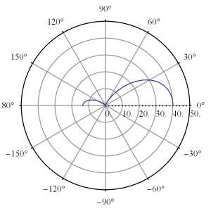
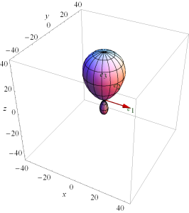
This array function is highly phase dependent, plotted for \( u_0 = 0 \) in fig. 1, and fig. 2.

ChebychevSecondMethodPolarFig3pn

fig 1. Plot with u_0 = 0, d = lambda/4

ChebychevSecondMethodSPolarFig4pn

fig 2. Spherical plot with u_0 = 0, d = lambda/4

This can be directed along a single direction (z-axis) with higher phase choices as illustrated in fig. 3, and fig. 4.


ChebychevSecondMethodPolarFig1pn

fig 3. Plot with u_0 = 3.5, d = 0.4 lambda

ChebychevSecondMethodSPolarFig2pn

fig 4. Spherical plot with u_0 = 3.5, d = 0.4 lambda


These can be explored interactively in this Mathematica Manipulate panel.

References

[1] Constantine A Balanis. Antenna theory: analysis and design. John Wiley \& Sons, 3rd edition, 2005.

Chebychev antenna array design

March 22, 2015 ece1229 , , , ,

[Click here for a PDF of this post with nicer formatting]

In our text [1] is a design procedure that applies Chebychev polynomials to the selection of current magnitudes for an evenly spaced array of identical antennas placed along the z-axis.

For an even number \( 2 M \) of identical antennas placed at positions \( \Br_m = (d/2) \lr{2 m -1} \Be_3 \), the array factor is

\begin{equation}\label{eqn:chebychevDesign:20}
\textrm{AF}
=
\sum_{m=-N}^N I_m e^{-j k \rcap \cdot \Br_m }.
\end{equation}

Assuming the currents are symmetric \( I_{-m} = I_m \), with \( \rcap = (\sin\theta \cos\phi, \sin\theta \sin\phi, \cos\theta ) \), and \( u = \frac{\pi d}{\lambda} \cos\theta \), this is

\begin{equation}\label{eqn:chebychevDesign:40}
\begin{aligned}
\textrm{AF}
&=
\sum_{m=-N}^N I_m e^{-j k (d/2) ( 2 m -1 )\cos\theta } \\
&=
2 \sum_{m=1}^N I_m \cos\lr{ k (d/2) ( 2 m -1)\cos\theta } \\
&=
2 \sum_{m=1}^N I_m \cos\lr{ (2 m -1) u }.
\end{aligned}
\end{equation}

This is a sum of only odd cosines, and can be expanded as a sum that includes all the odd powers of \( \cos u \). Suppose for example that this is a four element array with \( N = 2 \). In this case the array factor has the form

\begin{equation}\label{eqn:chebychevDesign:60}
\begin{aligned}
\textrm{AF}
&=
2 \lr{ I_1 \cos u + I_2 \lr{ 4 \cos^3 u – 3 \cos u } } \\
&=
2 \lr{ \lr{ I_1 – 3 I_2 } \cos u + 4 I_2 \cos^3 u }.
\end{aligned}
\end{equation}

The design procedure in the text sets \( \cos u = z/z_0 \), and then equates this to \( T_3(z) = 4 z^3 – 3 z \) to determine the current amplitudes \( I_m \). That is

\begin{equation}\label{eqn:chebychevDesign:80}
\frac{ 2 I_1 – 6 I_2 }{z_0} z + \frac{8 I_2}{z_0^3} z^3 = -3 z + 4 z^3,
\end{equation}

or

\begin{equation}\label{eqn:chebychevDesign:100}
\begin{aligned}
\begin{bmatrix}
I_1 \\
I_2
\end{bmatrix}
&=
{\begin{bmatrix}
2/z_0 & -6/z_0 \\
0 & 8/z_0^3
\end{bmatrix}}^{-1}
\begin{bmatrix}
-3 \\
4
\end{bmatrix} \\
&=
\frac{z_0}{2}
\begin{bmatrix}
3 (z_0^2 -1) \\
z_0^2
\end{bmatrix}.
\end{aligned}
\end{equation}

The currents in the array factor are fully determined up to a scale factor, reducing the array factor to

\begin{equation}\label{eqn:chebychevDesign:140}
\textrm{AF} = 4 z_0^3 \cos^3 u – 3 z_0 \cos u.
\end{equation}

The zeros of this array factor are located at the zeros of

\begin{equation}\label{eqn:chebychevDesign:120}
T_3( z_0 \cos u ) = \cos( 3 \cos^{-1} \lr{ z_0 \cos u } ),
\end{equation}

which are at \( 3 \cos^{-1} \lr{ z_0 \cos u } = \pi/2 + m \pi = \pi \lr{ m + \inv{2} } \)

\begin{equation}\label{eqn:chebychevDesign:160}
\cos u = \inv{z_0} \cos\lr{ \frac{\pi}{3} \lr{ m + \inv{2} } } = \setlr{ 0, \pm \frac{\sqrt{3}}{2 z_0} }.
\end{equation}

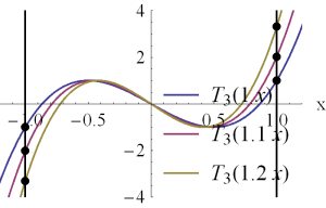
showing that the scaling factor \( z_0 \) effects the locations of the zeros. It also allows the values at the extremes \( \cos u = \pm 1 \), to increase past the \( \pm 1 \) non-scaled limit values. These effects can be explored in this Mathematica notebook, but can also be seen in fig. 1.

ChebyChevThreeScaledFig2pn

fig 1. T_3( z_0 x) for a few different scale factors z_0.


The scale factor can be fixed for a desired maximum power gain. For \( R
\textrm{dB} \), that will be when

\begin{equation}\label{eqn:chebychevDesign:180}
20 \log_{10} \cosh( 3 \cosh^{-1} z_0 ) = R \textrm{dB},
\end{equation}

or

\begin{equation}\label{eqn:chebychevDesign:200}
z_0 = \cosh \lr{ \inv{3} \cosh^{-1} \lr{ 10^{\frac{R}{20}} } }.
\end{equation}

For \( R = 30 \) dB (say), we have \( z_0 = 2.1 \), and

\begin{equation}\label{eqn:chebychevDesign:220}
\textrm{AF}
= 40 \cos^3 \lr{ \frac{\pi d}{\lambda} \cos\theta } – 6.4 \cos \lr{ \frac{\pi d}{\lambda} \cos\theta }.
\end{equation}

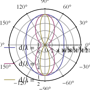
These are plotted in fig. 2 (linear scale), and fig. 3 (dB scale) for a couple values of \( d/\lambda \).

ChebychevT3FittingFig3pn

fig 2. T_3 fitting of 4 element array (linear scale).

ChebychevT3FittingDbFig4pn

fig 3. T_3 fitting of 4 element array (dB scale).

To explore the \( d/\lambda \) dependence try this Mathematica notebook.

References

[1] Constantine A Balanis. Antenna theory: analysis and design. John
Wiley & Sons, 3rd edition, 2005.