geometric product

A better 3D generalization of the Mandelbrot set.

February 9, 2021 math and physics play , , , , , , ,

I’ve been exploring 3D generalizations of the Mandelbrot set:

The iterative equation for the Mandelbrot set can be written in vector form ([1]) as:
\begin{equation}
\begin{aligned}
\Bz
&\rightarrow
\Bz \Be_1 \Bz + \Bc \\
&=
\Bz \lr{ \Be_1 \cdot \Bz }
+
\Bz \cdot \lr{ \Be_1 \wedge \Bz }
+ \Bc \\
&=
2 \Bz \lr{ \Be_1 \cdot \Bz }

\Bz^2\, \Be_1
+ \Bc
\end{aligned}
\end{equation}
Plotting this in 3D was an interesting challenge, but showed that the Mandelbrot set expressed above has rotational symmetry about the x-axis, which is kind of boring.

If all we require for a 3D fractal is to iterate a vector equation that is (presumably) at least quadratic, then we have lots of options. Here’s the first one that comes to mind:
\begin{equation}
\begin{aligned}
\Bz
&\rightarrow
\gpgradeone{ \Ba \Bz \Bb \Bz \Bc } + \Bd \\
&=
\lr{ \Ba \cdot \Bz } \lr{ \Bz \cross \lr{ \Bc \cross \Bz } }
+
\lr{ \Ba \cross \Bz } \lr{ \Bz \cdot \lr{ \Bc \cross \Bz } }
+ \Bd
.
\end{aligned}
\end{equation}
where we iterate starting, as usual with \( \Bz = 0 \) where \( \Bd \) is the point of interest to test for inclusion in the set. I tried this with
\begin{equation}\label{eqn:mandel3:n}
\begin{aligned}
\Ba &= (1,1,1) \\
\Bb &= (1,0,0) \\
\Bc &= (1,-1,0).
\end{aligned}
\end{equation}
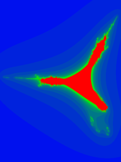
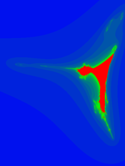
Here are some slice plots at various values of z

and an animation of the slices with respect to the z-axis:

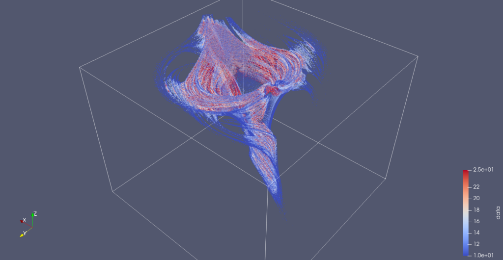
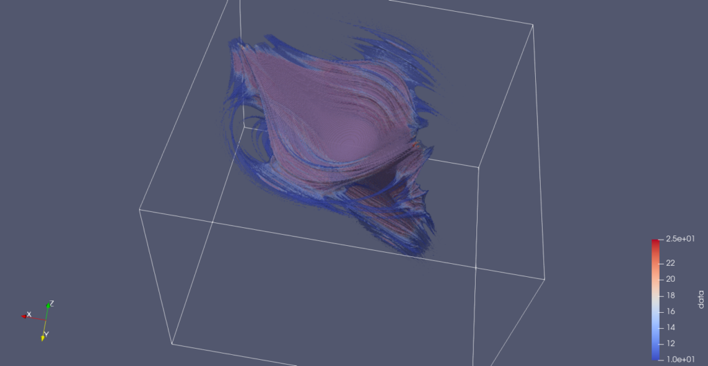
Here are a couple snapshots from a 3D Paraview rendering of a netCDF dataset of all the escape time values

Data collection and image creation used commit b042acf6ab7a5ba09865490b3f1fedaf0bd6e773 from my Mandelbrot generalization experimentation repository.

References

[1] L. Dorst, D. Fontijne, and S. Mann. Geometric Algebra for Computer Science. Morgan Kaufmann, San Francisco, 2007.

Some experiments in youtube mathematics videos

January 3, 2021 math and physics play , , , , , , ,

A couple years ago I was curious how easy it would be to use a graphics tablet as a virtual chalkboard, and produced a handful of very rough YouTube videos to get a feel for the basics of streaming and video editing (much of which I’ve now forgotten how to do). These were the videos in chronological order:

  • Introduction to Geometric (Clifford) Algebra.Introduction to Geometric (Clifford) algebra. Interpretation of products of unit vectors, rules for reducing products of unit vectors, and the axioms that justify those rules.
  • Geometric Algebra: dot, wedge, cross and vector products.Geometric (Clifford) Algebra introduction, showing the relation between the vector product dot and wedge products, and the cross product.
  • Solution of two line intersection using geometric algebra.
  • Linear system solution using the wedge product.. This video provides a standalone introduction to the wedge product, the geometry of the wedge product and some properties, and linear system solution as a sample application. In this video the wedge product is introduced independently of any geometric (Clifford) algebra, as an antisymmetric and associative operator. You’ll see that we get Cramer’s rule for free from this solution technique.
  • Exponential form of vector products in geometric algebra.In this video, I discussed the exponential form of the product of two vectors.

    I showed an example of how two unit vectors, each rotations of zcap orthonormal \(\mathbb{R}^3\) planes, produce a “complex” exponential in the plane that spans these two vectors.

  • Velocity and acceleration in cylindrical coordinates using geometric algebra.I derived the cylindrical coordinate representations of the velocity and acceleration vectors, showing the radial and azimuthal components of each vector.

    I also showed how these are related to the dot and wedge product with the radial unit vector.

  • Duality transformations in geometric algebra.Duality transformations (pseudoscalar multiplication) will be demonstrated in \(\mathbb{R}^2\) and \(\mathbb{R}^3\).

    A polar parameterized vector in \(\mathbb{R}^2\), written in complex exponential form, is multiplied by a unit pseudoscalar for the x-y plane. We see that the result is a vector normal to that vector, with the direction of the normal dependent on the order of multiplication, and the orientation of the pseudoscalar used.

    In \(\mathbb{R}^3\) we see that a vector multiplied by a pseudoscalar yields the bivector that represents the plane that is normal to that vector. The sign of that bivector (or its cyclic orientation) depends on the orientation of the pseudoscalar. The order of multiplication was not mentioned in this case since the \(\mathbb{R}^3\) pseudoscalar commutes with any grade object (assumed, not proved). An example of a vector with two components in a plane, multiplied by a pseudoscalar was also given, which allowed for a visualization of the bivector that is normal to the original vector.

  • Math bait and switch: Fractional integer exponents.When I was a kid, my dad asked me to explain fractional exponents, and perhaps any non-positive integer exponents, to him. He objected to the idea of multiplying something by itself \(1/2\) times.

    I failed to answer the question to his satisfaction. My own son is now reviewing the rules of exponentiation, and it occurred to me (30 years later) why my explanation to Dad failed.

    Essentially, there’s a small bait and switch required, and my dad didn’t fall for it.

    The meaning that my dad gave to exponentiation was that \( x^n\) equals \(x\) times itself \(n\) times.

    Using this rule, it is easy to demonstrate that \(x^a x^b = x^{a + b}\), and this can be used to justify expressions like \(x^{1/2}\). However, doing this really means that we’ve switched the definition of exponential, defining an exponential as any number that satisfies the relationship:

    \(x^a x^b = x^{a+b}\),

    where \(x^1 = x\). This slight of hand is required to give meaning to \(x^{1/2}\) or other exponentials where the exponential argument is any non-positive integer.

Of these videos I just relistened to the wedge product episode, as I had a new lone comment on it, and I couldn’t even remember what I had said. It wasn’t completely horrible, despite the low tech. I was, however, very surprised how soft and gentle my voice was. When I am talking math in person, I get very animated, but attempting to manage the tech was distracting and all the excitement that I’d normally have was obliterated.

I’d love to attempt a manim based presentation of some of this material, but suspect if I do something completely scripted like that, I may not be a very good narrator.

Updated notes for ece1229 antenna theory

March 16, 2015 ece1229 , , , , , , , , , , , , , , , , , , , , , , , , , , , , , , , , , , , , , , , , , , , , , , , , , , , , , , , , , , , , , , , , , , , , , , , , , , , , , , , , , , , , , , , , , , , , , , , , , , , , , , , , , , , , , , , , , , , , , , , , , , , , , , , , , , , , , , , , , , , , , , , , , , , , ,

I’ve now posted a first update of my notes for the antenna theory course that I am taking this term at UofT.

Unlike most of the other classes I have taken, I am not attempting to take comprehensive notes for this class. The class is taught on slides which go by faster than I can easily take notes for (and some of which match the textbook closely). In class I have annotated my copy of textbook with little details instead. This set of notes contains musings of details that were unclear, or in some cases, details that were provided in class, but are not in the text (and too long to pencil into my book), as well as some notes Geometric Algebra formalism for Maxwell’s equations with magnetic sources (something I’ve encountered for the first time in any real detail in this class).

The notes compilation linked above includes all of the following separate notes, some of which have been posted separately on this blog:

Image theorem

March 14, 2015 ece1229 , , , , , , , ,

[Click here for a PDF of this post with nicer formatting]

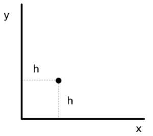
In the last problem set we examined the array factor for a corner cube configuration, shown in fig. 1.
 

homework3Fig1

fig. 1. A corner-cube antenna.


Motivation

This is a horizontal dipole antenna placed next to a metallic corner. The radiation at points in the interior of the cube have contributions due to the line of sight field from the antenna as well as reflections. We looked at an approximation of ground reflections using the \underlineAndIndex{Image Theorem}, modeling the ground as a perfectly conducting surface. I completely misunderstood that theorem and how it should be applied. As presented it seemed like a simple way to figure out the reflection characteristics. This confused me since it did not seem consistent with Fresnel reflection theory. I did try to reconcile to the two, but that reconciliation only appeared to work for certain dipole orientations, and that orientation dependence remained an open question.

It turns out that the idea of the Image Theorem is to find a source configuration that contains the specified source, but contains enough other sources that the tangential component of the electric field superposition is zero on the conducting surface, as required by Maxwell’s equations. This allows the boundary to be completely removed from the problem.

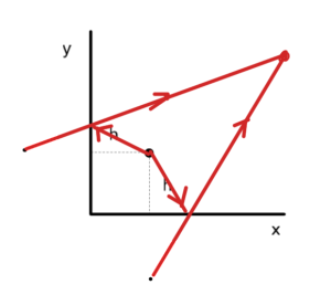
Thinking of the corner cube configuration as a reflection problem, I positioned sources as in fig. 2.
 

incorrectImagePlacementForCornerCubeFig2

fig. 2. Incorrect Image Theorem source placement for corner cube.


Because of the horizontal orientation of the dipole, I argued that the reflection coefficient should be -1. The reflection point is a bit messy to calculate, and it turns out to zeroth order in \( h/r \) the \( \sin\theta \) magnitude scaling of the reflected (far-field) field is present for both reflected rays. I though that this was probably because the observation point lays at the same altitude for both the line of sight ray and the reflected ray.

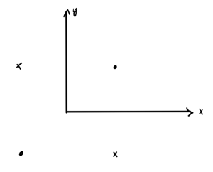
Attempting this problem as a reflection problem makes it much more difficult than it needs to be. It turns out that the correct image source placement for this problem is that of fig. 3.
 

cornerCubeImageSourcePlacementFig3

fig. 3. Correct image source placement for the corner cube.


This wasn’t at all obvious to me. The key is understanding that the goal of the image source placement isn’t to figure out how the reflection will occur, but to manufacture a source configuration for which the tangential component of the electric field is zero on the conducting surface.

Image placement for infinite conducting plane.

Before thinking about the corner cube configuration, consider a horizontal dipole next to an infinite conducting plane. This, and the correct image source placement is illustrated in fig. 4.
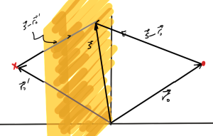
 

reflectionOfImagePointsFig1

fig. 4. Image source placement for horizontal dipole.


I’ll now verify that this is the correct image source. This is basically a calculation that the tangential components of the electric fields from both sources sum to zero.

Let,

\begin{equation}\label{eqn:imageTheorem:20}
r = \Abs{\Bs – \Br_0},
\end{equation}

so that the magnetic vector potential for the first quadrant dipole has the form

\begin{equation}\label{eqn:imageTheorem:40}
\BA = \frac{A_0}{4 \pi r} e^{-j k r} \zcap.
\end{equation}

With

\begin{equation}\label{eqn:imageTheorem:60}
\begin{aligned}
\kcap &= \frac{\Bs – \Br_0}{s} \\
\tilde{\BE} &= \zcap – \lr{\zcap \cdot \kcap} \kcap,
\end{aligned}
\end{equation}

the far-field electric field at the point \( \Bs \) on the plane is

\begin{equation}\label{eqn:imageTheorem:80}
\BE = -j \omega \frac{A_0}{4 \pi r} e^{-j k r} \tilde{\BE}.
\end{equation}

If the normal to the plane is \( \ncap \) the tangential component of this field is the projection of \( \BE \) on the direction

\begin{equation}\label{eqn:imageTheorem:100}
\pcap = \frac{\kcap \cross \ncap}{\Abs{\kcap \cross \ncap}}.
\end{equation}

That tangential component is directed along

\begin{equation}\label{eqn:imageTheorem:120}
\lr{\tilde{\BE} \cdot \pcap } \pcap
=
\lr{\lr{\zcap – \lr{\zcap \cdot \kcap} \kcap} \cdot \lr{\kcap \cross \ncap}} \frac{\kcap \cross \ncap}{\Abs{\kcap \cross \ncap}^2}.
\end{equation}

Because the triple product \( \kcap \cdot \lr{\kcap \cross \ncap} = 0 \), the tangential component of the electric field, provided \( \kcap \cdot \ncap \ne 0 \), is

\begin{equation}\label{eqn:imageTheorem:140}
\BE_\parallel
=
-j \omega \frac{A_0}{4 \pi r} e^{-j k r} \zcap \cdot \lr{\kcap \cross \ncap} \frac{\kcap \cross \ncap}{ 1 – \lr{ \ncap \cdot \kcap }^2 }.
\end{equation}

Now the wave vector direction for the second quadrant ray on the plane is required. Both \( \kcap’ \) and \( \Bs’ \) are reflections across the plane. Any such reflection has the value

\begin{equation}\label{eqn:imageTheorem:160}
\begin{aligned}
\Bx’
&= \lr{ \Bx \wedge \ncap} \ncap – \lr{ \Bx \cdot \ncap } \ncap \\
&= – \lr{ \ncap \wedge \Bx + \ncap \cdot \Bx } \ncap \\
&= – \ncap \Bx \ncap.
\end{aligned}
\end{equation}

This multivector product nicely encapsulates the reflection operation. Consider a reflection against the y-z plane with normal \( \Be_1 \) to verify that this works

\begin{equation}\label{eqn:imageTheorem:180}
\begin{aligned}
-\Be_1 \Bx \Be_1
&=
-\Be_1 \lr{ x \Be_1 + y \Be_2 + z \Be_3 } \Be_1 \\
&=
-\lr{ x – y \Be_2 \Be_1 + z \Be_3 \Be_1 } \Be_1 \\
&=
-\lr{ x \Be_1 – y \Be_2 + z \Be_3 } \\
&=
– x \Be_1 + y \Be_2 + z \Be_3.
\end{aligned}
\end{equation}

This has the x component flipped in sign and the rest left untouched as desired for a reflection in the y-z plane.

The second quadrant field will have \( \kcap’ \cross \ncap \) terms in place of all the \( \kcap \cross \ncap \) terms of \ref{eqn:imageTheorem:140}. We want to know how the two compare. This calculation is simply done using the dual form of the cross product temporarily

\begin{equation}\label{eqn:imageTheorem:200}
\begin{aligned}
\kcap’ \cross \ncap
&=
-I \lr{ \kcap’ \wedge \ncap} \\
&=
-I \gpgradetwo{\kcap’ \ncap} \\
&=
-I \gpgradetwo{ {-\ncap \kcap \ncap} \ncap} \\
&=
I \gpgradetwo{ \ncap \kcap } \\
&=
I \ncap \wedge \kcap \\
&=
-\ncap \cross \kcap \\
&=
\kcap \cross \ncap.
\end{aligned}
\end{equation}

So, provided the image source in the second quadrant is oppositely oriented (sign inversion), the tangential components of the two will sum to zero on that surface.

Thinking back to the corner cube, it is clear that an image source opposite to the source across from one of the walls will result in a zero tangential electric field along this boundary as is the case here (say the y-z plane). A second pair of sources opposite from each other anywhere else also about the y-z plane will not change that zero tangential electric field on this surface, but if the signs of the sources is alternated as in fig. 3 it will also result in zero tangential electric field on the z-x plane, which has the desired boundary value effects for both surfaces of the corner cube.

Notes for ece1229 antenna theory

February 4, 2015 ece1229 , , , , , , , , , , , , , , , , , , , , , , , , , , , , , , , , , , , , , , , , , , , , , , , , , , , , , , , , , , , , , , , , , , , , , , , , , , , , , , , , , , , ,

I’ve now posted a first set of notes for the antenna theory course that I am taking this term at UofT.

Unlike most of the other classes I have taken, I am not attempting to take comprehensive notes for this class. The class is taught on slides that match the textbook so closely, there is little value to me taking notes that just replicate the text. Instead, I am annotating my copy of textbook with little details instead. My usual notes collection for the class will contain musings of details that were unclear, or in some cases, details that were provided in class, but are not in the text (and too long to pencil into my book.)

The notes linked above include:

  • Reading notes for chapter 2 (Fundamental Parameters of Antennas) and chapter 3 (Radiation Integrals and Auxiliary Potential Functions) of the class text.
  • Geometric Algebra musings.  How to do formulate Maxwell’s equations when magnetic sources are also included (those modeling magnetic dipoles).
  • Some problems for chapter 2 content.