magnetic field

Constant magnetic solenoid field

September 24, 2015 phy1520 , , , , ,

[Click here for a PDF of this post with nicer formatting]

In [2] the following vector potential

\begin{equation}\label{eqn:solenoidConstantField:20}
\BA = \frac{B \rho_a^2}{2 \rho} \phicap,
\end{equation}

is introduced in a discussion on the Aharonov-Bohm effect, for configurations where the interior field of a solenoid is either a constant \( \BB \) or zero.

I wasn’t able to make sense of this since the field I was calculating was zero for all \( \rho \ne 0 \)

\begin{equation}\label{eqn:solenoidConstantField:40}
\begin{aligned}
\BB
&= \spacegrad \cross \BA \\
&= \lr{ \rhocap \partial_\rho + \zcap \partial_z + \frac{\phicap}{\rho}
\partial_\phi } \cross \frac{B \rho_a^2}{2 \rho} \phicap \\
&= \lr{ \rhocap \partial_\rho + \frac{\phicap}{\rho} \partial_\phi } \cross
\frac{B \rho_a^2}{2 \rho} \phicap \\
&=
\frac{B \rho_a^2}{2}
\rhocap \cross \phicap \partial_\rho \lr{ \inv{\rho} }
+
\frac{B \rho_a^2}{2 \rho}
\frac{\phicap}{\rho} \cross \partial_\phi \phicap \\
&=
\frac{B \rho_a^2}{2 \rho^2} \lr{ -\zcap + \phicap \cross \partial_\phi \phicap}.
\end{aligned}
\end{equation}

Note that the \( \rho \) partial requires that \( \rho \ne 0 \). To expand the cross product in the second term let \( j = \Be_1 \Be_2 \), and expand using a Geometric Algebra representation of the unit vector

\begin{equation}\label{eqn:solenoidConstantField:60}
\begin{aligned}
\phicap \cross \partial_\phi \phicap
&=
\Be_2 e^{j \phi} \cross \lr{ \Be_2 \Be_1 \Be_2 e^{j \phi} } \\
&=
– \Be_1 \Be_2 \Be_3
\gpgradetwo{
\Be_2 e^{j \phi} (-\Be_1) e^{j \phi}
} \\
&=
\Be_1 \Be_2 \Be_3 \Be_2 \Be_1 \\
&= \Be_3 \\
&= \zcap.
\end{aligned}
\end{equation}

So, provided \( \rho \ne 0 \), \( \BB = 0 \).

The errata [1] provides the clarification, showing that a \( \rho > \rho_a \) constraint is required for this potential to produce the desired results. Continuity at \( \rho = \rho_a \) means that in the interior (or at least on the boundary) we must have one of

\begin{equation}\label{eqn:solenoidConstantField:80}
\BA = \frac{B \rho_a}{2} \phicap,
\end{equation}

or

\begin{equation}\label{eqn:solenoidConstantField:100}
\BA = \frac{B \rho}{2} \phicap.
\end{equation}

The first doesn’t work, but the second does

\begin{equation}\label{eqn:solenoidConstantField:120}
\begin{aligned}
\BB
&= \spacegrad \cross \BA \\
&= \lr{ \rhocap \partial_\rho + \zcap \partial_z + \frac{\phicap}{\rho}
\partial_\phi } \cross \frac{B \rho}{2 } \phicap \\
&=
\frac{B }{2 } \rhocap \cross \phicap
+
\frac{B \rho}{2 }
\frac{\phicap}{\rho} \cross \partial_\phi \phicap \\
&= B \zcap.
\end{aligned}
\end{equation}

So the vector potential that we want for a constant \( B \zcap \) field in the interior \( \rho < \rho_a \) of a cylindrical space, we need

\begin{equation}\label{eqn:solenoidConstantField:140}
\BA =
\left\{
\begin{array}{l l}
\frac{B \rho_a^2}{2 \rho} \phicap & \quad \mbox{if \( \rho \ge \rho_a \) } \\
\frac{B \rho}{2} \phicap & \quad \mbox{if \( \rho \le \rho_a \).}
\end{array}
\right.
\end{equation}

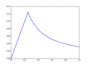
An example of the magnitude of potential is graphed in fig. 1.

solenoidPotentialFig1

fig. 1. Vector potential for constant field in cylindrical region.


References

[1] Jun John Sakurai and Jim J Napolitano. \emph{Errata: Typographical Errors, Mistakes, and Comments, Modern Quantum Mechanics, 2nd Edition}, 2013. URL http://www.rpi.edu/dept/phys/Courses/PHYS6520/Spring2015/ErrataMQM.pdf.

[2] Jun John Sakurai and Jim J Napolitano. Modern quantum mechanics. Pearson Higher Ed, 2014.

Plane wave solution directly from Maxwell’s equations

May 6, 2015 math and physics play , , , ,

[Click here for a PDF of this post with nicer formatting]

Here’s a problem that I thought was fun, an exercise for the reader to show that the plane wave solution to Maxwell’s equations can be found with ease directly from Maxwell’s equations. This is in contrast to the what seems like the usual method of first showing that Maxwell’s equations imply wave equations for the fields, and then solving those wave equations.

Problem. \( \xcap \) oriented plane wave electric field ([1] ex. 4.1)

A uniform plane wave having only an \( x \) component of the electric field is traveling in the \( + z \) direction in an unbounded lossless, source-0free region. Using Maxwell’s equations write expressions for the electric and corresponding magnetic field intensities.

Answer

The phasor form of Maxwell’s equations for a source free region are

\begin{equation}\label{eqn:ExPlaneWave:40}
\spacegrad \cross \BE = -j \omega \BB
\end{equation}
\begin{equation}\label{eqn:ExPlaneWave:60}
\spacegrad \cross \BH = j \omega \BD
\end{equation}
\begin{equation}\label{eqn:ExPlaneWave:80}
\spacegrad \cdot \BD = 0
\end{equation}
\begin{equation}\label{eqn:ExPlaneWave:100}
\spacegrad \cdot \BB = 0.
\end{equation}

Since \( \BE = \xcap E(z) \), the magnetic field follows from \ref{eqn:ExPlaneWave:40}

\begin{equation}\label{eqn:ExPlaneWave:120}
-j \omega \BB
= \spacegrad \cross \BE
=
\begin{vmatrix}
\xcap & \ycap & \zcap \\
\partial_x & \partial_y & \partial_z \\
E & 0 & 0
\end{vmatrix}
=
\ycap \partial_z E(z)
– \zcap \partial_y E(z),
\end{equation}

or

\begin{equation}\label{eqn:ExPlaneWave:140}
\BB =
-\inv{j \omega} \partial_z E.
\end{equation}

This is constrained by \ref{eqn:ExPlaneWave:60}

\begin{equation}\label{eqn:ExPlaneWave:160}
j \omega \epsilon \xcap E
=
\inv{\mu} \spacegrad \cross \BB
=
-\inv{\mu j \omega}
\begin{vmatrix}
\xcap & \ycap & \zcap \\
\partial_x & \partial_y & \partial_z \\
0 & \partial_z E & 0
\end{vmatrix}
=
-\inv{\mu j \omega}
\lr{
-\xcap \partial_{z z} E
+ \zcap \partial_x \partial_z E
}
\end{equation}

Since \( \partial_x \partial_z E = \partial_z \lr{ \partial_x E } = \partial_z \inv{\epsilon} \spacegrad \cdot \BD = \partial_z 0 \), this means

\begin{equation}\label{eqn:ExPlaneWave:180}
\partial_{zz} E = -\omega^2 \epsilon\mu E = -k^2 E.
\end{equation}

This is the usual starting place that we use to show that the plane wave has an exponential form

\begin{equation}\label{eqn:ExPlaneWave:200}
\BE(z) =
\xcap
\lr{
E_{+} e^{-j k z}
+
E_{-} e^{j k z}
}.
\end{equation}

The magnetic field from \ref{eqn:ExPlaneWave:140} is

\begin{equation}\label{eqn:ExPlaneWave:220}
\BB
= \frac{j}{\omega} \lr{ -j k E_{+} e^{-j k z} + j k E_{-} e^{j k z} }
= \inv{c} \lr{ E_{+} e^{-j k z} – E_{-} e^{j k z} },
\end{equation}

or

\begin{equation}\label{eqn:ExPlaneWave:240}
\BH
= \inv{\mu c} \lr{ E_{+} e^{-j k z} – E_{-} e^{j k z} }
= \inv{\eta} \lr{ E_{+} e^{-j k z} – E_{-} e^{j k z} }.
\end{equation}

A solution requires zero divergence for the magnetic field, but that can be seen to be the case by inspection.

References

[1] Constantine A Balanis. Advanced engineering electromagnetics. Wiley New York, 1989.

Updated notes for ece1229 antenna theory

March 16, 2015 ece1229 , , , , , , , , , , , , , , , , , , , , , , , , , , , , , , , , , , , , , , , , , , , , , , , , , , , , , , , , , , , , , , , , , , , , , , , , , , , , , , , , , , , , , , , , , , , , , , , , , , , , , , , , , , , , , , , , , , , , , , , , , , , , , , , , , , , , , , , , , , , , , , , , , , , , ,

I’ve now posted a first update of my notes for the antenna theory course that I am taking this term at UofT.

Unlike most of the other classes I have taken, I am not attempting to take comprehensive notes for this class. The class is taught on slides which go by faster than I can easily take notes for (and some of which match the textbook closely). In class I have annotated my copy of textbook with little details instead. This set of notes contains musings of details that were unclear, or in some cases, details that were provided in class, but are not in the text (and too long to pencil into my book), as well as some notes Geometric Algebra formalism for Maxwell’s equations with magnetic sources (something I’ve encountered for the first time in any real detail in this class).

The notes compilation linked above includes all of the following separate notes, some of which have been posted separately on this blog:

Parallel projection of electromagnetic fields with Geometric Algebra

March 8, 2015 ece1229 , , , ,

[Click here for a PDF of this post with nicer formatting]

When computing the components of a polarized reflecting ray that were parallel or not-parallel to the reflecting surface, it was found that the electric and magnetic fields could be written as

\begin{equation}\label{eqn:gaFieldProjection:280}
\BE = \lr{ \BE \cdot \pcap } \pcap + \lr{ \BE \cdot \qcap } \qcap = E_\parallel \pcap + E_\perp \qcap
\end{equation}
\begin{equation}\label{eqn:gaFieldProjection:300}
\BH = \lr{ \BH \cdot \pcap } \pcap + \lr{ \BH \cdot \qcap } \qcap = H_\parallel \pcap + H_\perp \qcap.
\end{equation}

where a unit vector \( \pcap \) that lies both in the reflecting plane and in the electromagnetic plane (tangential to the wave vector direction) was

\begin{equation}\label{eqn:gaFieldProjection:340}
\pcap = \frac{\kcap \cross \ncap}{\Abs{\kcap \cross \ncap}}
\end{equation}
\begin{equation}\label{eqn:gaFieldProjection:360}
\qcap = \kcap \cross \pcap.
\end{equation}

Here \( \qcap \) is perpendicular to \( \pcap \) but lies in the electromagnetic plane. This logically subdivides the fields into two pairs, one with the electric field parallel to the reflection plane

\begin{equation}\label{eqn:gaFieldProjection:240}
\begin{aligned}
\BE_1 &= \lr{ \BE \cdot \pcap } \pcap = E_\parallel \pcap \\
\BH_1 &= \lr{ \BH \cdot \qcap } \qcap = H_\perp \qcap,
\end{aligned}
\end{equation}

and one with the magnetic field parallel to the reflection plane

\begin{equation}\label{eqn:gaFieldProjection:380}
\begin{aligned}
\BH_2 &= \lr{ \BH \cdot \pcap } \pcap = H_\parallel \pcap \\
\BE_2 &= \lr{ \BE \cdot \qcap } \qcap = E_\perp \qcap.
\end{aligned}
\end{equation}

Expressed in Geometric Algebra form, each of these pairs of fields should be thought of as components of a single multivector field. That is

\begin{equation}\label{eqn:gaFieldProjection:400}
F_1 = \BE_1 + c \mu_0 \BH_1 I
\end{equation}
\begin{equation}\label{eqn:gaFieldProjection:460}
F_2 = \BE_2 + c \mu_0 \BH_2 I
\end{equation}

where the original total field is

\begin{equation}\label{eqn:gaFieldProjection:420}
F = \BE + c \mu_0 \BH I.
\end{equation}

In \ref{eqn:gaFieldProjection:400} we have a composite projection operation, finding the portion of the electric field that lies in the reflection plane, and simultaneously finding the component of the magnetic field that lies perpendicular to that (while still lying in the tangential plane of the electromagnetic field). In \ref{eqn:gaFieldProjection:460} the magnetic field is projected onto the reflection plane and a component of the electric field that lies in the tangential (to the wave vector direction) plane is computed.

If we operate only on the complete multivector field, can we find these composite projection field components in a single operation, instead of working with the individual electric and magnetic fields?

Working towards this goal, it is worthwhile to point out consequences of the assumption that the fields are plane wave (or equivalently far field spherical waves). For such a wave we have

\begin{equation}\label{eqn:gaFieldProjection:480}
\begin{aligned}
\BH
&= \inv{\mu_0} \kcap \cross \BE \\
&= \inv{\mu_0} (-I)\lr{ \kcap \wedge \BE } \\
&= \inv{\mu_0} (-I)\lr{ \kcap \BE – \kcap \cdot \BE} \\
&= -\frac{I}{\mu_0} \kcap \BE,
\end{aligned}
\end{equation}

or

\begin{equation}\label{eqn:gaFieldProjection:520}
\mu_0 \BH I = \kcap \BE.
\end{equation}

This made use of the identity \( \Ba \wedge \Bb = I \lr{\Ba \cross \Bb} \), and the fact that the electric field is perpendicular to the wave vector direction. The total multivector field is

\begin{equation}\label{eqn:gaFieldProjection:500}
\begin{aligned}
F
&= \BE + c \mu_0 \BH I \\
&= \lr{ 1 + c \kcap } \BE.
\end{aligned}
\end{equation}

Expansion of magnetic field component that is perpendicular to the reflection plane gives

\begin{equation}\label{eqn:gaFieldProjection:540}
\begin{aligned}
\mu_0 H_\perp
&= \mu_0 \BH \cdot \qcap \\
&= \gpgradezero{ \lr{-\kcap \BE I} \qcap } \\
&= -\gpgradezero{ \kcap \BE I \lr{ \kcap \cross \pcap} } \\
&= \gpgradezero{ \kcap \BE I I \lr{ \kcap \wedge \pcap} } \\
&= -\gpgradezero{ \kcap \BE \kcap \pcap } \\
&= \gpgradezero{ \kcap \kcap \BE \pcap } \\
&= \BE \cdot \pcap,
\end{aligned}
\end{equation}

so

\begin{equation}\label{eqn:gaFieldProjection:560}
F_1
= (\pcap + c I \qcap ) \BE \cdot \pcap.
\end{equation}

Since \( \qcap \kcap \pcap = I \), the component of the complete multivector field in the \( \pcap \) direction is

\begin{equation}\label{eqn:gaFieldProjection:580}
\begin{aligned}
F_1
&= (\pcap – c \pcap \kcap ) \BE \cdot \pcap \\
&= \pcap (1 – c \kcap ) \BE \cdot \pcap \\
&= (1 + c \kcap ) \pcap \BE \cdot \pcap.
\end{aligned}
\end{equation}

It is reasonable to expect that \( F_2 \) has a similar form, but with \( \pcap \rightarrow \qcap \). This is verified by expansion

\begin{equation}\label{eqn:gaFieldProjection:600}
\begin{aligned}
F_2
&= E_\perp \qcap + c \lr{ \mu_0 H_\parallel } \pcap I \\
&= \lr{\BE \cdot \qcap} \qcap + c \gpgradezero{ – \kcap \BE I \kcap \qcap I } \lr{\kcap \qcap I} I \\
&= \lr{\BE \cdot \qcap} \qcap + c \gpgradezero{ \kcap \BE \kcap \qcap } \kcap \qcap (-1) \\
&= \lr{\BE \cdot \qcap} \qcap + c \gpgradezero{ \kcap \BE (-\qcap \kcap) } \kcap \qcap (-1) \\
&= \lr{\BE \cdot \qcap} \qcap + c \gpgradezero{ \kcap \kcap \BE \qcap } \kcap \qcap \\
&= \lr{ 1 + c \kcap } \qcap \lr{ \BE \cdot \qcap }
\end{aligned}
\end{equation}

This and \ref{eqn:gaFieldProjection:580} before that makes a lot of sense. The original field can be written

\begin{equation}\label{eqn:gaFieldProjection:620}
F = \lr{ \Ecap + c \lr{ \kcap \cross \Ecap } I } \BE \cdot \Ecap,
\end{equation}

where the leading multivector term contains all the directional dependence of the electric and magnetic field components, and the trailing scalar has the magnitude of the field with respect to the reference direction \( \Ecap \).

We have the same structure after projecting \( \BE \) onto either the \( \pcap \), or \( \qcap \) directions respectively

\begin{equation}\label{eqn:gaFieldProjection:660}
F_1 = \lr{ \pcap + c \lr{ \kcap \cross \pcap } I} \BE \cdot \pcap
\end{equation}
\begin{equation}\label{eqn:gaFieldProjection:680}
F_2 = \lr{ \qcap + c \lr{ \kcap \cross \qcap } I} \BE \cdot \qcap.
\end{equation}

The next question is how to achieve this projection operation directly in terms of \( F \) and \( \pcap, \qcap \), without resorting to expression of \( F \) in terms of \( \BE \), and \( \BB \). I’ve not yet been able to determine the structure of that operation.

Maxwell’s equations in tensor form with magnetic sources

February 22, 2015 ece1229 , , , , , , , , , , , , , , , , , , , , , , , , ,

[Click here for a PDF of this post with nicer formatting]

Following the principle that one should always relate new formalisms to things previously learned, I’d like to know what Maxwell’s equations look like in tensor form when magnetic sources are included. As a verification that the previous Geometric Algebra form of Maxwell’s equation that includes magnetic sources is correct, I’ll start with the GA form of Maxwell’s equation, find the tensor form, and then verify that the vector form of Maxwell’s equations can be recovered from the tensor form.

Tensor form

With four-vector potential \( A \), and bivector electromagnetic field \( F = \grad \wedge A \), the GA form of Maxwell’s equation is

\begin{equation}\label{eqn:gaMagneticSourcesToTensorToVector:20}
\grad F = \frac{J}{\epsilon_0 c} + M I.
\end{equation}

The left hand side can be unpacked into vector and trivector terms \( \grad F = \grad \cdot F + \grad \wedge F \), which happens to also separate the sources nicely as a side effect

\begin{equation}\label{eqn:gaMagneticSourcesToTensorToVector:60}
\grad \cdot F = \frac{J}{\epsilon_0 c}
\end{equation}
\begin{equation}\label{eqn:gaMagneticSourcesToTensorToVector:80}
\grad \wedge F = M I.
\end{equation}

The electric source equation can be unpacked into tensor form by dotting with the four vector basis vectors. With the usual definition \( F^{\alpha \beta} = \partial^\alpha A^\beta – \partial^\beta A^\alpha \), that is

\begin{equation}\label{eqn:gaMagneticSourcesToTensorToVector:100}
\begin{aligned}
\gamma^\mu \cdot \lr{ \grad \cdot F }
&=
\gamma^\mu \cdot \lr{ \grad \cdot \lr{ \grad \wedge A } } \\
&=
\gamma^\mu \cdot \lr{ \gamma^\nu \partial_\nu \cdot
\lr{ \gamma_\alpha \partial^\alpha \wedge \gamma_\beta A^\beta } } \\
&=
\gamma^\mu \cdot \lr{ \gamma^\nu \cdot \lr{ \gamma_\alpha \wedge \gamma_\beta
} } \partial_\nu \partial^\alpha A^\beta \\
&=
\inv{2}
\gamma^\mu \cdot \lr{ \gamma^\nu \cdot \lr{ \gamma_\alpha \wedge \gamma_\beta } }
\partial_\nu F^{\alpha \beta} \\
&=
\inv{2} \delta^{\nu \mu}_{[\alpha \beta]} \partial_\nu F^{\alpha \beta} \\
&=
\inv{2} \partial_\nu F^{\nu \mu}

\inv{2} \partial_\nu F^{\mu \nu} \\
&=
\partial_\nu F^{\nu \mu}.
\end{aligned}
\end{equation}

So the first tensor equation is

\begin{equation}\label{eqn:gaMagneticSourcesToTensorToVector:120}
\boxed{
\partial_\nu F^{\nu \mu} = \inv{c \epsilon_0} J^\mu.
}
\end{equation}

To unpack the magnetic source portion of Maxwell’s equation, put it first into dual form, so that it has four vectors on each side

\begin{equation}\label{eqn:gaMagneticSourcesToTensorToVector:140}
\begin{aligned}
M
&= – \lr{ \grad \wedge F} I \\
&= -\frac{1}{2} \lr{ \grad F + F \grad } I \\
&= -\frac{1}{2} \lr{ \grad F I – F I \grad } \\
&= – \grad \cdot \lr{ F I }.
\end{aligned}
\end{equation}

Dotting with \( \gamma^\mu \) gives

\begin{equation}\label{eqn:gaMagneticSourcesToTensorToVector:160}
\begin{aligned}
M^\mu
&= \gamma^\mu \cdot \lr{ \grad \cdot \lr{ – F I } } \\
&= \gamma^\mu \cdot \lr{ \gamma^\nu \partial_\nu \cdot \lr{ -\frac{1}{2}
\gamma^\alpha \wedge \gamma^\beta I F_{\alpha \beta} } } \\
&= -\inv{2}
\gpgradezero{
\gamma^\mu \cdot \lr{ \gamma^\nu \cdot \lr{ \gamma^\alpha \wedge \gamma^\beta I } }
}
\partial_\nu F_{\alpha \beta}.
\end{aligned}
\end{equation}

This scalar grade selection is a complete antisymmetrization of the indexes

\begin{equation}\label{eqn:gaMagneticSourcesToTensorToVector:180}
\begin{aligned}
\gpgradezero{
\gamma^\mu \cdot \lr{ \gamma^\nu \cdot \lr{ \gamma^\alpha \wedge \gamma^\beta I } }
}
&=
\gpgradezero{
\gamma^\mu \cdot \lr{ \gamma^\nu \cdot \lr{
\gamma^\alpha \gamma^\beta
\gamma_0 \gamma_1 \gamma_2 \gamma_3
} }
} \\
&=
\gpgradezero{
\gamma_0 \gamma_1 \gamma_2 \gamma_3
\gamma^\mu \gamma^\nu \gamma^\alpha \gamma^\beta
} \\
&=
\delta^{\mu \nu \alpha \beta}_{3 2 1 0} \\
&=
\epsilon^{\mu \nu \alpha \beta },
\end{aligned}
\end{equation}

so the magnetic source portion of Maxwell’s equation, in tensor form, is

\begin{equation}\label{eqn:gaMagneticSourcesToTensorToVector:200}
\boxed{
\inv{2} \epsilon^{\nu \alpha \beta \mu}
\partial_\nu F_{\alpha \beta}
=
M^\mu.
}
\end{equation}

Relating the tensor to the fields

The electromagnetic field has been identified with the electric and magnetic fields by

\begin{equation}\label{eqn:gaMagneticSourcesToTensorToVector:220}
F = \boldsymbol{\mathcal{E}} + c \mu_0 \boldsymbol{\mathcal{H}} I ,
\end{equation}

or in coordinates

\begin{equation}\label{eqn:gaMagneticSourcesToTensorToVector:240}
\inv{2} \gamma_\mu \wedge \gamma_\nu F^{\mu \nu}
= E^a \gamma_a \gamma_0 + c \mu_0 H^a \gamma_a \gamma_0 I.
\end{equation}

By forming the dot product sequence \( F^{\alpha \beta} = \gamma^\beta \cdot \lr{ \gamma^\alpha \cdot F } \), the electric and magnetic field components can be related to the tensor components. The electric field components follow by inspection and are

\begin{equation}\label{eqn:gaMagneticSourcesToTensorToVector:260}
E^b = \gamma^0 \cdot \lr{ \gamma^b \cdot F } = F^{b 0}.
\end{equation}

The magnetic field relation to the tensor components follow from

\begin{equation}\label{eqn:gaMagneticSourcesToTensorToVector:280}
\begin{aligned}
F^{r s}
&= F_{r s} \\
&= \gamma_s \cdot \lr{ \gamma_r \cdot \lr{ c \mu_0 H^a \gamma_a \gamma_0 I
} } \\
&=
c \mu_0 H^a \gpgradezero{ \gamma_s \gamma_r \gamma_a \gamma_0 I } \\
&=
c \mu_0 H^a \gpgradezero{ -\gamma^0 \gamma^1 \gamma^2 \gamma^3
\gamma_s \gamma_r \gamma_a \gamma_0 } \\
&=
c \mu_0 H^a \gpgradezero{ -\gamma^1 \gamma^2 \gamma^3
\gamma_s \gamma_r \gamma_a } \\
&=
– c \mu_0 H^a \delta^{[3 2 1]}_{s r a} \\
&=
c \mu_0 H^a \epsilon_{ s r a }.
\end{aligned}
\end{equation}

Expanding this for each pair of spacelike coordinates gives

\begin{equation}\label{eqn:gaMagneticSourcesToTensorToVector:320}
F^{1 2} = c \mu_0 H^3 \epsilon_{ 2 1 3 } = – c \mu_0 H^3
\end{equation}
\begin{equation}\label{eqn:gaMagneticSourcesToTensorToVector:340}
F^{2 3} = c \mu_0 H^1 \epsilon_{ 3 2 1 } = – c \mu_0 H^1
\end{equation}
\begin{equation}\label{eqn:gaMagneticSourcesToTensorToVector:360}
F^{3 1} = c \mu_0 H^2 \epsilon_{ 1 3 2 } = – c \mu_0 H^2,
\end{equation}

or

\begin{equation}\label{eqn:gaMagneticSourcesToTensorToVector:380}
\boxed{
\begin{aligned}
E^1 &= F^{1 0} \\
E^2 &= F^{2 0} \\
E^3 &= F^{3 0} \\
H^1 &= -\inv{c \mu_0} F^{2 3} \\
H^2 &= -\inv{c \mu_0} F^{3 1} \\
H^3 &= -\inv{c \mu_0} F^{1 2}.
\end{aligned}
}
\end{equation}

Recover the vector equations from the tensor equations

Starting with the non-dual Maxwell tensor equation, expanding the timelike index gives

\begin{equation}\label{eqn:gaMagneticSourcesToTensorToVector:480}
\begin{aligned}
\inv{c \epsilon_0} J^0
&= \inv{\epsilon_0} \rho \\
&=
\partial_\nu F^{\nu 0} \\
&=
\partial_1 F^{1 0}
+\partial_2 F^{2 0}
+\partial_3 F^{3 0}
\end{aligned}
\end{equation}

This is Gauss’s law

\begin{equation}\label{eqn:gaMagneticSourcesToTensorToVector:500}
\boxed{
\spacegrad \cdot \boldsymbol{\mathcal{E}}
=
\rho/\epsilon_0.
}
\end{equation}

For a spacelike index, any one is representive. Expanding index 1 gives

\begin{equation}\label{eqn:gaMagneticSourcesToTensorToVector:520}
\begin{aligned}
\inv{c \epsilon_0} J^1
&= \partial_\nu F^{\nu 1} \\
&= \inv{c} \partial_t F^{0 1}
+ \partial_2 F^{2 1}
+ \partial_3 F^{3 1} \\
&= -\inv{c} E^1
+ \partial_2 (c \mu_0 H^3)
+ \partial_3 (-c \mu_0 H^2) \\
&=
\lr{ -\inv{c} \PD{t}{\boldsymbol{\mathcal{E}}} + c \mu_0 \spacegrad \cross \boldsymbol{\mathcal{H}} } \cdot \Be_1.
\end{aligned}
\end{equation}

Extending this to the other indexes and multiplying through by \( \epsilon_0 c \) recovers the Ampere-Maxwell equation (assuming linear media)

\begin{equation}\label{eqn:gaMagneticSourcesToTensorToVector:540}
\boxed{
\spacegrad \cross \boldsymbol{\mathcal{H}} = \boldsymbol{\mathcal{J}} + \PD{t}{\boldsymbol{\mathcal{D}}}.
}
\end{equation}

The expansion of the 0th free (timelike) index of the dual Maxwell tensor equation is

\begin{equation}\label{eqn:gaMagneticSourcesToTensorToVector:400}
\begin{aligned}
M^0
&=
\inv{2} \epsilon^{\nu \alpha \beta 0}
\partial_\nu F_{\alpha \beta} \\
&=
-\inv{2} \epsilon^{0 \nu \alpha \beta}
\partial_\nu F_{\alpha \beta} \\
&=
-\inv{2}
\lr{
\partial_1 (F_{2 3} – F_{3 2})
+\partial_2 (F_{3 1} – F_{1 3})
+\partial_3 (F_{1 2} – F_{2 1})
} \\
&=

\lr{
\partial_1 F_{2 3}
+\partial_2 F_{3 1}
+\partial_3 F_{1 2}
} \\
&=

\lr{
\partial_1 (- c \mu_0 H^1 ) +
\partial_2 (- c \mu_0 H^2 ) +
\partial_3 (- c \mu_0 H^3 )
},
\end{aligned}
\end{equation}

but \( M^0 = c \rho_m \), giving us Gauss’s law for magnetism (with magnetic charge density included)

\begin{equation}\label{eqn:gaMagneticSourcesToTensorToVector:420}
\boxed{
\spacegrad \cdot \boldsymbol{\mathcal{H}} = \rho_m/\mu_0.
}
\end{equation}

For the spacelike indexes of the dual Maxwell equation, only one need be computed (say 1), and cyclic permutation will provide the rest. That is

\begin{equation}\label{eqn:gaMagneticSourcesToTensorToVector:440}
\begin{aligned}
M^1
&= \inv{2} \epsilon^{\nu \alpha \beta 1} \partial_\nu F_{\alpha \beta} \\
&=
\inv{2} \lr{ \partial_2 \lr{F_{3 0} – F_{0 3}} }
+\inv{2} \lr{ \partial_3 \lr{F_{0 2} – F_{0 2}} }
+\inv{2} \lr{ \partial_0 \lr{F_{2 3} – F_{3 2}} } \\
&=
– \partial_2 F^{3 0}
+ \partial_3 F^{2 0}
+ \partial_0 F_{2 3} \\
&=
-\partial_2 E^3 + \partial_3 E^2 + \inv{c} \PD{t}{} \lr{ – c \mu_0 H^1 } \\
&= – \lr{ \spacegrad \cross \boldsymbol{\mathcal{E}} + \mu_0 \PD{t}{\boldsymbol{\mathcal{H}}} } \cdot \Be_1.
\end{aligned}
\end{equation}

Extending this to the rest of the coordinates gives the Maxwell-Faraday equation (as extended to include magnetic current density sources)

\begin{equation}\label{eqn:gaMagneticSourcesToTensorToVector:460}
\boxed{
\spacegrad \cross \boldsymbol{\mathcal{E}} = -\boldsymbol{\mathcal{M}} – \mu_0 \PD{t}{\boldsymbol{\mathcal{H}}}.
}
\end{equation}

This takes things full circle, going from the vector differential Maxwell’s equations, to the Geometric Algebra form of Maxwell’s equation, to Maxwell’s equations in tensor form, and back to the vector form. Not only is the tensor form of Maxwell’s equations with magnetic sources now known, the translation from the tensor and vector formalism has also been verified, and miraculously no signs or factors of 2 were lost or gained in the process.